A signal jammer circuit floods the same radio frequencies a phone uses with low-power RF noise, cutting the link between handset and cell tower. Here is how the RF amplifier, oscillator, and tuning stage fit together, what range they reach, and why operating one is illegal in the US.
What Is a Signal Jammer and What Does It Do?
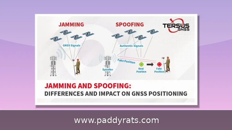
A signal jammer is basically an electronic device that cuts off communication between a cell phone and a base station. It does this by transmitting low-power radio signals on the same frequencies your phone relies on, creating strong interference between the caller and the receiver. In security terms, that's a denial-of-service attack: the RF noise overwhelms the original signals from cell towers and satellites, so the receiver can no longer pick out the real transmission.
This setup will jam UMTS, 3G, CDMA, GSM, and PHS networks, and the same basic idea applies to GPS, WiFi, and drone control links too. You'll see these devices sold or described under plenty of different names — cell jammers, mobile phone jammers, signal blockers, GPS jammers, text stoppers, RF jammers, radio frequency blockers, noise jammers, protocol jammers, full spectrum jammers. The labels vary, but they all come down to the same thing: drowning the channel in more noise than the network can handle.
How Does a Signal Jammer Circuit Work?
Honestly, the basic idea behind how a jammer works is simpler than most people expect. A tuned circuit generates a radio signal at whatever frequency you're going after, an amplifier boosts that signal to a usable power level, and an antenna pushes it out into the air. Because the jammer is broadcasting on the same frequency band your phone relies on, the handset's receiver picks up a wall of noise instead of the tower's signal — and the call or data connection just drops.
Three subcircuits do most of the work here: an RF amplifier, a voltage controlled oscillator (VCO), and a tuning circuit. Wire those together and you've got a functioning cell phone jammer circuit. The oscillator is what generates the carrier signal, the tuning stage sets which frequency that carrier lands on, and then the amplifier boosts it enough to actually interfere with a nearby handset, rather than just sitting there doing nothing.
In a typical ElectronicsForU-style build, once transistor Q1 turns on, the tuned circuit at its collector starts to oscillate. That tuned circuit is really just capacitor C1 and inductor L1 working together, and since they act like an oscillator with almost zero resistance, they produce a very high frequency with very little damping. The basic idea goes like this: voltage builds up in the capacitor, and once it's fully charged, that charge flows through the inductor, which stores magnetic energy that matches the voltage across the capacitor. This constant exchange of energy back and forth between the two is what keeps the oscillation running.
The Three Essential Jammer Subcircuits
Each of these subcircuits has its own job to do, and leaving even one out means the whole thing won't jam a single signal. The table below breaks down what each stage actually does, along with the parts that typically handle that job in a basic design.
| Subcircuit | Function | Typical Parts |
|---|---|---|
| RF amplifier | Boosts the oscillator signal to a level that can interfere with a handset | Transistor Q1, capacitors C4 and C5, resistor R1 |
| Voltage controlled oscillator | Generates the RF carrier at the target band | Tuned circuit of C1 and L1 |
| Tuning circuit | Sets and trims the exact jamming frequency | 22pF trimmer, inductor L1 |
The amplifier stage is what takes the weak signal coming out of the tuned circuit and boosts its amplitude. From there, the amplified signal travels to the antenna through capacitor C6, which blocks DC and lets only the AC component through. Leave out that coupling capacitor and you run into trouble: DC from the supply would leak into the antenna, and the RF output would suffer as a result. As for the tuning stage, it's what gives a builder the freedom to shift the output onto 700MHz, 900MHz, or whatever specific band they're after, instead of just spraying noise across the entire spectrum.
Key Components and Their Roles in the Circuit
In a basic cell phone jammer build, every part has a fairly specific job to do. Resistor R1 takes care of emitter loading, while R2 handles base biasing for the transistor. Capacitor C1 works together with the inductor to generate the frequency, and C2 and C3 supply the feedback that keeps the oscillator running. C4 is there to cut down noise, C5 and C6 manage coupling between stages, and C7 handles decoupling so that supply noise doesn't leak into the RF path. The actual amplification comes from transistor Q1, and inductor L1 completes the tuned circuit alongside C1.
The RF amplifier stage centers on transistor Q1, along with capacitors C4 and C5 and resistor R1. Its role is to take the signal produced by the tuned circuit and strengthen it, after which the amplified signal travels to the antenna by way of capacitor C6. When Q1 turns ON, the tuned circuit at the collector turns ON as well, and that's the point where oscillation begins. Because the tuned circuit behaves like an oscillator with essentially zero resistance, it produces a very high frequency with only minimal damping — exactly the kind of behavior you want if a stable carrier matters.
Here's something to keep in mind when you're looking at a schematic: C1 and L1 together determine the resonant frequency, so changing either one shifts you to a different band. That's precisely why real builds tend to include trimmers and adjustable inductors — they let you fine-tune the output after the circuit is assembled, rather than just assuming your calculated values will land exactly where you want them.
How to Calculate the Required Jamming Frequency
Frequency selection starts with the target network. A cell phone jammer has to match the band the handset is actually using, which in most markets means covering 700MHz, 800MHz, 900MHz, 1800MHz, 1900MHz, and 2100MHz for 2G through 5G service. GPS sits at 1575MHz, while WiFi occupies 2.4GHz and 5GHz. An ideal RF jamming device features 22pF trimmers to block the RF noise signal and should cover 50 MHz to 1 GHz; forcing it to jam from 500 MHz most likely causes stability issues.
The table below lists the common bands a jammer is designed to hit and what each one is used for.
| Band | Primary Use |
|---|---|
| 700 / 800 / 900 MHz | 2G, 3G, and some 4G cellular service |
| 1800 / 1900 / 2100 MHz | 4G LTE and 5G cellular service |
| 1575 MHz | GPS reception |
| 2.4 / 5 GHz | WiFi and Bluetooth |
Peak resonance is found empirically rather than by formula alone. Attach a DC voltmeter (0–10 volts) to the test point and ground, then tinker with the 22p trimmer until you get a maximum meter reading of about 3V. Once you hit that peak, fine-tune the trimmer to shift the output back to the proper frequency. This is the step most beginners skip, and it is the reason a circuit that looks correct on paper can still fail to jam anything in practice.
DIY RF Jammer: Coil, Flyback and Antenna Steps
For builders working from a documented design, the physical construction matters as much as the schematic. The coil should measure 1mm in thickness with 0.1 mm magnetic wire. The secondary winding gives 8–9 mm sparks, which requires a 20W power supply to sustain. Before antenna installation, sparks measured 2–3 mm; with a 2-meter antenna attached, spark length rises to about 8mm, and the pre-made jammer then operates at roughly 10–15 meters.
Range is not uniform across bands. A simple jammer circuit can jam a wide range of RF signals between 5 and 10 meters. MW noise is likely at longer distances, while VHF noise is most prevalent at 8–10 meters. That asymmetry is normal: lower frequencies travel farther for the same power, so the effective radius depends heavily on which band you are targeting and how the antenna is tuned.
Two signal detectors, each with a dipole antenna, choke, and diode, are often used to verify the build. Each dipole antenna is tuned to 900MHz, and when the antennas resonate at 900 MHz, jamming occurs. That gives builders a concrete pass/fail test instead of guessing whether the circuit is radiating at all.
Types, Pricing, and Real-World Range
Commercial jammers come in several form factors. Portable signal jammers are small handheld battery-powered cordless units with built-in antennas, which makes them easy to carry but limits their output. Pricier units add more antennas, directional coverage, or higher power for larger rooms and vehicles.
| Model | Targets | Price |
|---|---|---|
| 4G Phone Jammer JM021 | Mobile phone, WiFi, GPS, LoJack | $520.00 |
| Drone UAV Signal Jammer JM004 | Drone command links (directional antennas) | $2,399.99 |
| Handheld WiFi Bluetooth Jammer JM012 | 2.4 / 5.2 / 5.8 GHz | $569.99 |
| Handheld Mobile Phone Jammer JM018 | 16 antennas, 25 meters | $699.00 |
Drone jammers deserve a separate note because their purpose is different from phone jamming. They break the command link between operator and aircraft so the drone either hovers in place or returns to its launch point. That is a safety and counter-surveillance use case rather than a privacy one, and it explains why UAV units cost several times more than a handheld phone jammer.
On the academic side, a student project using a PIC16F877A microcontroller controls a jammer circuit that blocks GSM, DCS, and CDMA signals for a set period using real-time clock functionality, with switches to select the network and set start and stop times. It is a good demonstration of how the RF stage and the control logic are separate problems that can be solved independently.
Are Signal Jammers Legal?
No — it is illegal to sell, advertise, distribute, or operate cell signal jammers in the United States and much of the world. The FCC states that jamming equipment poses serious risks to critical public safety communications, can prevent 9-1-1 and other emergency calls, and interferes with law enforcement communications. Radio frequencies are legally protected by the Communications Act of 1934, which is the statute the FCC cites when enforcing against sellers and users alike.
A jammer also interferes with GPS, WiFi, and police radar, so the collateral damage goes well beyond the phone call someone was trying to block. Jammers block signal boosters as well; amplifiers cannot stop jammers, because the booster is trying to amplify a signal that has already been drowned out. Detection is difficult, and the most common symptom is simply dropped service that comes back when you move.
The best response is to relocate, since jamming range is usually no more than about 30 square feet for a handheld unit, or to contact law enforcement or file an FCC complaint. If you are dealing with persistent interference in a building, documenting the times and locations and reporting it is far more effective than trying to fight the signal with more hardware.
Limitations and Practical Takeaways
The stated objective of most jamming projects is to block mobile phone and radio signals for security within a limited range. The limitations are equally clear: a build only blocks certain frequency bands, and coverage varies by mobile carrier and region — a design tuned for networks in one country may not touch the bands used in another. In Nigeria, for example, carrier band assignments differ enough that a generic build may miss the networks in use.
Power, antenna tuning, and component tolerance all cap real-world performance. A circuit that jams at 10 meters indoors may do nothing at 30 meters outdoors, and a trimmer that drifts will move the output off the intended band. Between the legal exposure and the technical constraints, the honest takeaway is that jamming circuits are worth studying as RF engineering, but building or operating one for actual use carries serious federal penalties in the US.
Frequently Asked Questions
How does a signal jammer circuit work?
A jammer transmits low-power RF noise on the same frequencies a phone uses, creating a denial-of-service attack that drowns out the link between handset and base station. Three subcircuits are essential: an RF amplifier, a voltage controlled oscillator, and a tuning circuit.
What components are needed to build a cell phone jammer?
A basic build uses transistor Q1 for amplification, resistors R1 and R2, capacitors C1 through C7 for frequency generation, feedback, coupling, and decoupling, plus inductor L1 and an antenna. The tuned circuit of C1 and L1 acts as the oscillator that sets the jamming frequency.
Are signal jammers legal?
It is illegal to sell, advertise, distribute, or operate cell signal jammers in the United States and much of the world. The FCC says jamming interferes with authorized radio communications, can block 9-1-1 emergency calls, and is outlawed under the Communications Act of 1934.
What range does a DIY RF jammer cover?
A simple jammer circuit can jam a wide range of RF signals between 5 and 10 meters. Adding a 2-meter antenna extends spark length and gives a range of roughly 10 to 15 meters, with VHF noise most prevalent at 8 to 10 meters.