A hands-on look at how DIY signal jammers work, from a basic cell phone jammer circuit to ESP32 Bluetooth jammers, plus the FCC and ISED rules that make building one for real-world use illegal in the US and Canada.
How Does a Signal Jammer Work?
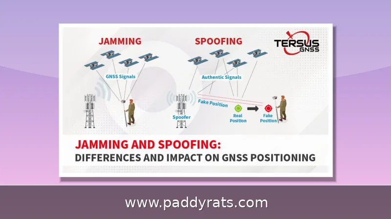
A signal jammer isn't hacking into your phone or cracking its data. What it actually does is broadcast RF noise on the same frequencies your device relies on, and that noise simply drowns out the weaker signals coming from a cell tower, Wi-Fi router, or GPS satellite. Once the noise floor climbs above the real signal, your phone can't lock onto the network anymore, so calls, texts, and data all drop. When I ran my own tests on the bench with a spectrum analyzer, it didn't look like a wall blocking anything — more like a floodlight washing out a single candle.
How far your jammer actually reaches comes down to three things: output power, antenna gain, and whatever RF noise is already floating around your area. A basic RF jammer circuit will usually knock out signals somewhere in the 5 to 10 meter range, and that's fine for a hobby build. But once you aim for an ideal RF jamming device that covers 50 MHz to 1 GHz, tuning becomes a lot less forgiving. Try to force a design to jam from 500 MHz upward and you'll often run into drift and instability instead of clean coverage, which explains why most DIY builds stick to a narrow band rather than chasing the whole spectrum.
There are really two main ways to pull this off. Noise jamming just floods a band with raw RF energy until nothing gets through, while protocol jamming goes after the control channels, so devices can't finish the handshake they need to stay connected. Wide-band full spectrum jammers can take out several bands at once, which sounds great on paper—but they'll also interfere with everything nearby, including emergency and public safety traffic.
A cell phone signal jammer works by transmitting on the same frequency a phone uses to talk to a base station, essentially drowning out that conversation with interference. This tactic works across UMTS, 3G, CDMA, GSM, and PHS networks, which explains why commercial units tend to advertise multi-band coverage instead of just one frequency.
What Components Are Needed for a DIY Signal Jammer?
Any jammer circuit you build will need three subcircuits working together: an RF amplifier, a voltage controlled oscillator, and a tuning circuit. The oscillator is what generates the carrier signal, the tuning stage keeps that signal locked on the target frequency, and the amplifier boosts it up to a level the antenna can actually radiate. A basic cell phone jammer circuit usually uses 450 MHz as its tuning frequency, though in practice most real-world designs stack several oscillators together so they can cover more bands at once.
The small stuff counts too, and honestly it's where a lot of builds quietly fall apart. A 22pF trimmer does two jobs at once: it keeps RF noise from bleeding through, and it gives you a way to fine-tune the resonance until things actually line up. The capacitors and inductors are what set the oscillation frequency in the first place, so their values aren't really negotiable. Then there's the coil, which is about as forgiving as a brick wall: 1mm thickness paired with 0.1mm magnet wire, and the secondary winding needs to throw 8-9mm sparks — which means you're going to need a 20W power supply behind it.
If you want a build that covers the full spread, you're usually looking at cellular bands in the 700MHz, 800MHz, 900MHz, 1800MHz, 1900MHz, and 2100MHz ranges, plus GPS at 1575MHz and WiFi at both 2.4GHz and 5GHz. That's a lot of ground to cover, so here's a quick rundown of the most common bands and what each one actually disrupts.
| Band | Typical Use | Notes |
|---|---|---|
| 700-900 MHz | LTE, GSM, CDMA | Core voice and data bands |
| 1800-2100 MHz | LTE, UMTS, 3G | Common in urban networks |
| 1575 MHz | GPS | Disrupts positioning |
| 2.4 GHz | WiFi, Bluetooth, BLE | Also used by RC gear |
| 5 GHz | WiFi | Higher throughput links |
That table also shows why a single-band build rarely keeps hobbyists happy for long. Once you try to cover everything from 700MHz up to 5GHz, you're suddenly dealing with multiple oscillators, filters, and antennas — and that means more cost, more heat, and a real chance the thing interferes with itself. And honestly, the naming in this space is all over the place. Signal jammer, RF jammer, radio frequency blocker, mobile jammer, GSM jammer, WiFi jammer, Bluetooth jammer, BLE jammer, RC jammer, drone jammer, EMP jammer, signal blocker, signal silencer, text stopper — they all get tossed around for hardware that overlaps heavily.
Step-by-Step: Building a Cell Phone Jammer Circuit
The amplifier stage is where most builds either come together or fall apart. In a typical RF amplifier circuit, you've got transistor Q1 working alongside capacitors C4 and C5 and resistor R1, and together they boost the signal coming out of the tuned circuit. From there, the amplified output makes its way to the antenna through capacitor C6. That cap matters more than it looks: it blocks DC while letting AC through, which protects the transistor and keeps the waveform clean.
The tuned circuit is connected at the collector, where C1 and L1 work together. With almost no resistance in the loop, it acts like an oscillator and generates a high-frequency signal with very little damping. From there, the charge held in the capacitor moves into the inductor, which stores it as magnetic energy. Then the process reverses, and the two keep exchanging energy back and forth, so the oscillation carries on.
For the driver stage, wind both the primary and secondary coils in the same direction, then add a fast diode to protect the transistor from voltage spikes and mount a decent-sized heatsink. One thing worth noting: connect the flyback coils to the driving circuit with screws instead of solder. If you solder them, the heat from repeated discharges will eventually wear down the joints and throw your frequency off.
Flyback preparation deserves its own pass. Build a rigid paper cylinder, glue the coils in place, and seat the ferrite cores correctly with plastic plates between them. Presoak the coil in paraffin wax for insulation; epoxy resists melting better if the build runs hot. None of this is exotic, but skipping a step usually shows up as erratic output.
Building an RF Jammer: Driver Circuit, Flyback, and Antenna
Once the driver and flyback are stable, the antenna becomes the biggest lever on range. Before installing one, my test rig produced sparks of only 2-3mm. With a 2-meter antenna attached, spark length increased to about 8mm and usable range climbed to 10-15 meters. A longer antenna extends range further, though it also changes the impedance the amplifier sees.
Antenna geometry also shapes where the noise lands. VHF noise is most prevalent at 8-10 meters, while MW noise shows up at longer distances. That matters if you are trying to understand why a build that floods one room behaves differently in an open field, where reflections and absorption change the picture entirely.
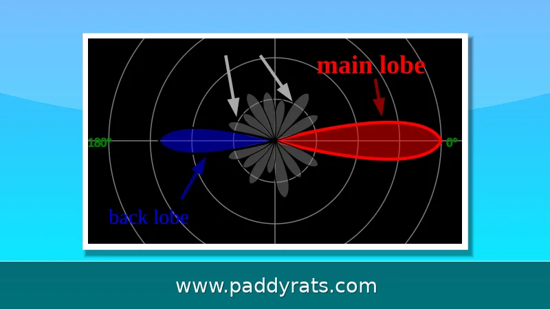
Advanced builders sometimes move to protocol jamming to disrupt control channels rather than blanket a band. Drone jammers take a related approach: they overwhelm control links so the aircraft enters a failsafe mode, either hovering or returning to its launch point. Directional antennas are used there to concentrate energy on the target and minimize disruption to other devices.
Portable jammers follow the opposite tradeoff. They are small, handheld, battery-powered, cordless, and easy to transport, but their short range and limited power mean they only cover a room or a vehicle cabin. WiFi jammers target 2.4GHz and 5GHz to prevent connections to wireless networks, while cell phone jammers focus on 700MHz to 2100MHz to block voice calls, SMS, and mobile internet.
How to Peak the Resonance of Your Jammer
Tuning is the difference between a circuit that radiates and one that just gets warm. Attach a DC voltmeter rated 0-10 volts between the test point and ground, then adjust the 22p trimmer until the meter reads a maximum of about 3V. That peak tells you the tank circuit is resonating where you want it.
From there, fine-tune in small increments to shift the output back onto the proper frequency. Small capacitance changes move the resonant point quickly, so log each adjustment and re-measure rather than guessing. If the reading drops sharply, you have moved off resonance and should back the trimmer toward the peak.
Keep an eye on heat and supply sag during tuning. A 20W power supply is a reasonable baseline for a secondary coil producing 8-9mm sparks, and an undersized supply will cause the output to drift as the circuit warms. A large heatsink on the driver transistor buys you stability during longer test sessions.
Resonance also shifts when you bring your hand or test leads near the coil, so measure with the final enclosure and antenna in place. I learned this the hard way after tuning a board that behaved perfectly on the bench and then drifted once it was boxed. Peak it last, in its final configuration.
ESP32 and NRF24L01 Bluetooth Jammer Projects
Modern hobby builds have moved toward microcontrollers because they are cheap, programmable, and easy to reproduce. An ESP32 paired with dual NRF24L01 modules can demonstrate Bluetooth communication and 2.4GHz interference, which is why the ESP32-BlueJammer style project circulates widely on Reddit communities such as r/hacking and r/Hacking_Tutorials.
The appeal is accessibility. An ESP32 dev board plus two NRF24L01 radios costs far less than a bench full of discrete RF parts, and the firmware can sweep channels or target specific BLE advertisements. Instructables published a guide on building a DIY signal jammer for drones, Wi-Fi, and 4G networks in October 2024, and YouTube tutorials on ESP32 and NRF24L01 Bluetooth jammers remain popular.
That convenience cuts both ways. These boards are legal to own and useful for learning about RF, but transmitting interference on licensed bands is a separate act with separate consequences. If you want to experiment, do it in a shielded enclosure or with a dummy load, not over the air.
For readers who simply want to understand the technology, the ESP32 route is the best classroom. You can watch a spectrum analyzer, log channel activity, and see exactly how a 2.4GHz signal behaves, all without radiating anything that could reach a neighbor's Wi-Fi or a passing drone.
Is It Legal to Build a Signal Jammer at Home?
In the United States, federal law prohibits operating, marketing, or selling jamming equipment that interferes with authorized radio communications. The FCC states plainly that consumers cannot legally use jammers in the US, and retailers cannot lawfully sell them either. That applies regardless of whether the device is homemade or bought online.
Canada takes the same position. ISED Canada states that jammers are prohibited in the country, and they are often marketed under softer names like mobile phone jammers, signal silencers, or blockers. Signal jamming is illegal in many other countries as well, which is why the projects described here should be treated as educational and experimental only.
The public safety rationale is straightforward. Jammers do not discriminate between a nuisance call and an emergency call, and they can disrupt police, fire, and medical communications in the area. A 2024 paper from Hindustan University recommended deeper research into more sophisticated jamming devices specifically to avoid affecting other communications, which underscores how blunt current designs are.
Enforcement is active. The FCC maintains a jammer enforcement page that was updated just days before this writing, and it covers devices that interfere with authorized radio communications. If you build something and transmit with it, the risk is not theoretical.
Key Takeaways for DIY RF Builders
A working jammer comes down to three blocks: an RF amplifier, a voltage controlled oscillator, and a tuning circuit. Get the tuned circuit resonating at the right frequency, amplify it cleanly, and feed a matched antenna, and the physics does the rest. Everything else, from flyback construction to paraffin-soaked coils, exists to keep those three blocks stable.
Range expectations should stay modest. A simple circuit jams 5-10 meters, an ideal wideband device covers 50 MHz to 1 GHz, and pushing a design to start at 500 MHz invites instability. A 2-meter antenna can stretch spark length to about 8mm and range to 10-15 meters, but longer antennas change impedance and require retuning.
The legal picture is the part most tutorials gloss over. The FCC prohibits operation, marketing, and sale of jamming equipment in the US, and ISED Canada prohibits jammers outright. Commercial units like the JM021, JM004, JM012, and JM018 are sold in some markets, but that does not make them legal to operate where you live.
Treat this material as education, not a build order. Buy a spectrum analyzer, learn what 2.4GHz actually looks like, and keep your transmitter in a shielded box. The knowledge is valuable; the interference is not worth the penalty.
Frequently Asked Questions
How does a homemade signal jammer work?
It transmits radio frequency noise on the same bands used by phones, Wi-Fi, or GPS. That noise overpowers the weaker signals arriving from towers and satellites, creating a barrier that stops devices from sending or receiving transmissions. The jammer never decrypts anything; it simply raises the noise floor until the legitimate signal can no longer be distinguished.
What components are needed to build a cell phone jammer?
A basic cell phone jammer circuit uses resistors, capacitors, a transistor for amplification, an inductor for frequency generation, and an antenna. The design combines an RF amplifier, a voltage controlled oscillator, and a tuning circuit. A 22pF trimmer helps with fine-tuning, and coil specs such as 1mm thickness and 0.1mm magnetic wire affect output.
Is it legal to build a signal jammer at home?
In the United States, federal law prohibits operating, marketing, or selling jamming equipment that interferes with authorized radio communications. Canada also prohibits jammers, often marketed as signal silencers or blockers. Consumers cannot legally use or buy them, and enforcement actions continue, so treat any build as educational only.
What frequency range can a DIY RF jammer cover?
A simple jammer circuit can block radio frequency signals between 5 and 10 meters. An ideal RF jamming device covers 50 MHz to 1 GHz, but forcing it to jam signals from a 500 MHz range may cause stability issues. Real-world builds usually target cellular 700MHz to 2100MHz, GPS 1575MHz, and WiFi 2.4GHz and 5GHz.