A hands-on look at how an educational signal jammer project actually works, from the RF amplifier and VCO tuning circuit to GSM 900 specs, FPGA and ESP8266 builds, and the hard legal line the FCC draws.
What Is a Signal Jammer and How Does It Work?
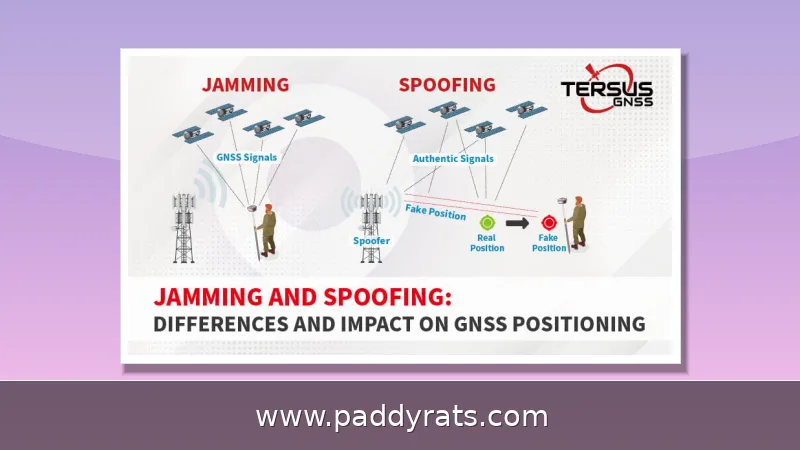
A signal jammer is, at its core, just a transmitter that deliberately drowns out the radio link between your phone and the cell tower. It pulls this off by broadcasting energy on the exact same frequency your phone is using, which raises the noise floor until the handset simply can't pick out the tower's signal anymore. Walk into that jammed zone and your phone will show no service, even in places where you'd normally have full bars.
When students or hobbyists write up their builds, they usually report success across a whole range of network types, both older and current ones — UMTS, 3G, CDMA, GSM, and PHS. That actually makes sense, because jamming isn't about going after one brand or carrier. It's about matching whatever frequencies the network happens to use. The same project write-ups also make it clear how much range really matters. A compact design can only reliably disrupt GSM communication within about 5 to 10 meters, which is enough for a single room or a small testing bench and not much else. But once you move up to a remote controlled tri-band unit, the described coverage jumps from 800 to 2100 MHz, so one device can reach across several bands at the same time. That gap pretty much sums up the trade-off builders keep running into: the wider the band coverage, the more complexity, power, and regulatory exposure you're signing up for.
There's serious money in this space, and the market numbers back it up. Technavio released a 169-page report in May 2024 projecting that the signal jammer market will grow by USD 1.08 billion between 2023 and 2028, at a CAGR of 5.66%, with year-over-year growth of 5.27% from 2023 to 2024. That kind of steady climb isn't surprising when you factor in demand from security, law enforcement, and industrial users, even as regulators keep tightening the rules around how these devices can be used. A separate report from Dataintelo paints an even rosier picture, valuing the market at $2.8 billion in 2025 and projecting it will reach $5.6 billion by 2034, growing at an 8.1% CAGR. The two forecasts don't line up perfectly, largely because they define the market differently and rely on different methods, but they're clearly pointing in the same direction: this is a growing global market, not just some niche hobbyist thing.
The terminology in this space gets messy fast, because search results tend to lump together several device families that don't actually work the same way. You'll run into signal jammer, cell phone jammer, mobile phone jammer, signal blocker, WiFi jammer, GSM jammer, EMP jammer, deauther, portable signal jammer, and multi-frequency jammer—and plenty of articles use them almost interchangeably. That's misleading. A deauther, for instance, doesn't jam radio traffic at all in the classic sense; it sends forged WiFi management frames that kick devices off a network. A GSM jammer, on the other hand, goes after licensed cellular bands, which is why the two raise very different technical and legal questions. Keeping the labels straight matters before you start comparing build guides, specs, or market reports, since a project labeled "jammer" could be anything from a 5–10 meter GSM blocker to an ESP8266 board that only disrupts WiFi connections.
Core Subcircuits: RF Amplifier, VCO, and Tuning Circuit
Every basic design I've come across in university reports and DIY guides boils down to the same three subcircuits: an RF amplifier, a voltage controlled oscillator, and a tuning circuit. The RF amplifier's job is to take the weak signal coming out of the tuned circuit and boost it enough that it can actually radiate. In most layouts, a single transistor (usually labeled Q1) does the heavy lifting, working alongside capacitors C4 and C5 and resistor R1 to amplify that signal. From there, the amplified output travels to the antenna through C6, a coupling capacitor that blocks DC while letting the AC signal pass through cleanly. That last part matters more than it might seem at first glance, because without C6, DC from the amplifier could leak into the antenna and throw off the entire stage. So in essence, each of the three parts handles one specific job, and together they form the backbone that every more complex jammer design is built on top of.
The tuned circuit is what sets the jammer's output frequency, and it really comes down to two parts working together: capacitor C1 and inductor L1. Pair them up and they form an oscillator that behaves almost as if it has zero resistance, so it can generate a very high frequency with very little damping — meaning the signal keeps going instead of fading out. What sustains that output is a constant back-and-forth exchange of energy. Voltage charges C1, the capacitor then discharges through L1, and the inductor briefly stores that energy as a magnetic field. Once the field collapses, the energy flows back into the capacitor and the cycle repeats. This loop runs on its own, holding the oscillation steady at the tuned frequency. Change the values of C1 or L1 and you shift that frequency, which is exactly how a build targeting 450 MHz, or the GSM 900 band (935 to 960 MHz), ends up with its specific operating range.
Once you look past those three core subcircuits, it becomes pretty clear that a finished jammer isn't just one clever circuit—it's really a small system of blocks that all have to work together. Check any standard build list and you'll see the same lineup every time: a voltage controlled oscillator, a tuning circuit, a noise generator, an RF amplification unit, a transmitting antenna, and a power source. Each one has its own job. The VCO sets the carrier, the tuning circuit keeps it locked on target, the noise generator creates the interfering signal, the RF amplifier boosts it up to a usable power level, and the antenna radiates it out into the air. When it comes to jamming techniques, they usually fall into three categories: noise jamming, pulse jamming, and directed energy methods—while frequency hopping and spread spectrum approaches tend to appear in both hardware and software builds. That last point is worth keeping in mind if you're a student, because the same concept can be implemented either with analog parts or with code running on a microcontroller. If you want to see how all the blocks fit together, the table below maps each one to its purpose and the technique it typically supports.
| Block | Primary Role | Typical Technique |
|---|---|---|
| Voltage controlled oscillator | Generates the carrier at the target band | Noise jamming, pulse jamming |
| Tuning circuit | Sets and stabilizes the operating frequency | Frequency hopping support |
| Noise generator | Creates the interfering signal | Noise jamming |
| RF amplification unit | Boosts signal to usable power | Directed energy methods |
| Transmitting antenna | Radiates the jamming signal | All techniques |
| Power source | Supplies stable operating voltage | All techniques |
Design parameters are what separate a working bench prototype from something that only looks good on paper: frequency bands, desired coverage distance, jamming-to-signal ratio, and power calculations. Get the jamming-to-signal ratio wrong and the whole thing falls apart — the device might trace a beautiful waveform on the scope, but the moment you test it in a real environment, it just won't hold up.
Building a Basic Cell Phone Jammer: Components and Steps
If you're approaching this as an electronics exercise rather than trying to actually deploy something, the build order is honestly pretty straightforward. You start with the three subcircuits that make the whole thing work — the RF amplifier, the voltage controlled oscillator (VCO), and the tuning circuit — and then wire them together in a chain that ends at the transmitting antenna. Every stage has one clear job. The VCO generates the oscillating signal, the tuning circuit locks in the target frequency, and the RF amplifier boosts that signal enough for it to actually radiate. One documented student build managed to block cell phone signals with 450MHz as the tuning frequency, which shows the concept holds up even at a smaller scale. Other frequency ranges follow the exact same design logic — you're mostly just swapping out component values, like the capacitor and inductor in the tuned circuit, to shift the band you're operating on. That's the nice thing about this layout: the same basic setup can be adapted for GSM 900 or multi-band designs without having to rebuild everything from scratch.
Parts choices tend to vary from one project to the next, and that flexibility is a big part of why a basic jammer build works so well as a learning exercise. Take one student GSM project: it paired an NE555 timer chip with transistors, capacitors, and resistors, then handled the control side in Visual Basic. A 555 timer cell phone jammer design trims things down even more, using noticeably fewer parts — which is exactly why it shows up so often as a first build for beginners. If you want a concrete place to start, one documented circuit lists R1, R2, C1 through C7, transistor Q1, and inductor L1 as its entire bill of materials. It's a short, cheap list that covers the essentials without much waste.
If you've spent any time digging through project archives, you've probably run into the same three approaches over and over. The table below breaks down what each one actually does well, so you can get a quick sense of which route fits your build before diving into the details.
GSM 900 and Multi-Frequency Jammer Specifications
A GSM 900 jammer targets the band used by all well-known carriers, stated as 935 to 960 MHz. Portable jammer projects typically target GSM 900 services plus other frequencies, and they are designed, built, and tested as complete units rather than partial circuits. Multi-frequency capability usually means covering several bands simultaneously, with safety features intended to prevent overuse or unintended interference.
Control and signal-generation specs are where these projects get interesting. A common module setup runs at an input voltage of 3.3V with a maximum operating speed of 500kbps, supports 2-FSK, GFSK, and MSK modulation, and allows a modifiable baud rate. The MCP4725 module adds 12-bit resolution for precision analog signal generation, which is useful when you need repeatable tuning.
GPS-related work in the same academic space uses Simulink to generate signals, with C/A code and navigation data communicating at up to 4.5 Mbps. Portable units are generally described as user-friendly, very easy to operate, with a simple ON-OFF switch and a conditioning display.
The table below puts the headline specifications side by side so the trade-offs are easier to see.
FPGA and ESP8266 Jammer Project Approaches
Two project styles dominate recent archives. The first is the software-defined route: a ResearchGate FPGA jammer graduation project report dated March 27, 2025 demonstrates that jamming logic can be implemented in programmable hardware, which makes frequency hopping and spread spectrum techniques far easier to experiment with than discrete analog stages.
The second is the microcontroller route. An Instructables ESP8266 WiFi jammer deauther project uses a FireBeetle board, and Hackster.io published a highly flexible mobile phone jammer PCB module with Proteus simulation on January 28, 2022. These builds are popular because the hardware is cheap and the firmware is easy to modify, but they also blur the line between a learning exercise and an actual interference device.
If you are choosing a direction for a course project, pick the approach that matches what you want to demonstrate. The table below maps each route to its strengths.
Jamming Indicators and Real-World Effects
The most reliable real-world indicator is behavioral rather than technical: you cannot communicate in areas where radio or cell coverage is typically good. If a phone that normally holds five bars suddenly reports no service across multiple carriers at the same spot, that pattern is consistent with interference rather than a network outage.
Schools are sometimes described as using signal jammers that block all signals including WiFi, with 5GHz WiFi potentially an exception because it runs on different frequencies. That exception is worth remembering, because it shows how band-specific these devices are: a jammer tuned for one range may leave another range completely untouched.
Engineering students frequently ask for help designing their own signal jammer for coursework, and that demand is exactly why the legal section below matters. Understanding the mechanism is legitimate education. Building and operating a working transmitter is a different act with a different legal status.
Risks, Compliance, and Limitations
The FCC is unambiguous on this point: operating RF jammers is a violation of federal law, with no exceptions for personal, commercial, or educational use. That is not a gray area or a licensing question. The FCC Jammer Enforcement page, which was updated just days before this article was researched, restates the prohibition, and the DHS Science and Technology jamming page dated September 3, 2025 describes the operational risks in detail.
The public safety angle is the most serious limitation. Jammers can interfere with public safety communications, leaving first responders without vital communications and critical situational awareness during an emergency. Legal issues surrounding cellular phone jammers stem largely from that potential to disrupt essential communication services, which is why regulations governing jammer use are stringent and government agencies actively monitor implementation.
Market dynamics are shaped by the same tension. Radio frequency restrictions and electromagnetic interference concerns constrain where these products can legally be sold and used, even as demand grows. A university report recommendation puts it well: further and deeper research is needed to produce more sophisticated jamming devices that do not affect other services.
My practical advice for anyone doing an educational project is to keep the work on the bench. Simulate the circuit, study the VCO tuning behavior, document the frequency math, and skip the antenna. The learning outcome is identical, and you avoid a federal enforcement problem entirely.
Educational Signal Jammer Project: Build, Working, and Legal Limits
| Project approach | Core components | Best for |
|---|---|---|
| 555 timer build | NE555 timer, transistors, capacitors, resistors | First-time learning with minimal parts |
| GSM 900 portable unit | VCO, tuning circuit, RF amplifier, antenna | Studying the 935-960 MHz band and coverage distance |
| ESP8266 deauther | FireBeetle board, firmware | Software and WiFi frame experiments |
| FPGA implementation | Programmable logic, Simulink-generated signals | Frequency hopping and spread spectrum research |
Whichever route you take, the same three subcircuits and the same legal boundary apply. The technical knowledge transfers across all four approaches, and the FCC rule does not.
How does a cell phone signal jammer work?
A jammer uses the same frequency as a mobile handset to create strong interference between the phone and the base station. It combines an RF amplifier, a voltage controlled oscillator, and a tuning circuit, so phones within range show no network available.
What frequency does a GSM 900 jammer target?
A GSM 900 jammer targets the GSM 900 band used by major carriers. One documented design tunes to 450MHz as its tuning frequency, and the same approach is applied to other frequency ranges. The GSM900 band range is stated as 935 to 960 MHz.
Is it legal to build or use a signal jammer?
No. The FCC states that operating RF jammers is a violation of federal law, with no exceptions for personal, commercial, or educational use. Jammers can also interfere with public safety communications, leaving responders without vital communications and situational awareness.
What components are needed for a basic jammer circuit?
A basic circuit uses resistors, capacitors, a transistor for amplification, an inductor for frequency generation, and an antenna. A documented build lists R1, R2, C1 through C7, transistor Q1, and inductor L1, plus a NE555 timer chip in a student GSM project.
Frequently Asked Questions
How does a cell phone signal jammer work?
A jammer uses the same frequency as a mobile handset to create strong interference between the phone and the base station. It combines an RF amplifier, a voltage controlled oscillator, and a tuning circuit, so phones within range show no network available.
What frequency does a GSM 900 jammer target?
A GSM 900 jammer targets the GSM 900 band used by major carriers. One documented design tunes to 450MHz as its tuning frequency, and the same approach is applied to other frequency ranges. The GSM900 band range is stated as 935 to 960 MHz.
Is it legal to build or use a signal jammer?
No. The FCC states that operating RF jammers is a violation of federal law, with no exceptions for personal, commercial, or educational use. Jammers can also interfere with public safety communications, leaving responders without vital communications and situational awareness.
What components are needed for a basic jammer circuit?
A basic circuit uses resistors, capacitors, a transistor for amplification, an inductor for frequency generation, and an antenna. A documented build lists R1, R2, C1 through C7, transistor Q1, and inductor L1, plus a NE555 timer chip in a student GSM project.