A signal jammer block diagram breaks a jammer into three core subcircuits: an RF amplifier, a voltage controlled oscillator, and a tuning circuit. This guide explains how those blocks connect, how they flood a receiver with interference, and where the legal lines sit.
What Is a Signal Jammer Block Diagram?
A signal jammer block diagram is basically a stripped-down map of what's going on inside a device that intentionally blocks radio communication. Rather than tracing every single solder joint, it breaks the circuit into a handful of labeled blocks: the oscillator that generates a radio frequency, the tuning network that decides which frequency actually gets produced, the RF amplifier that boosts that signal up to a usable power level, and the antenna that radiates it out. You'll usually see a power supply section drawn in alongside these stages too.
A signal jammer block diagram is really just a way to make a complicated circuit easier to grasp at a glance. Rather than asking you to trace every wire and component value, it groups the device into a few functional stages and shows how a cell phone jammer circuit moves from a low-level oscillation to a transmitted interfering signal. That kind of clarity helps a pretty broad audience: students putting together project reports, hobbyists breadboarding their first RF circuit, and technical writers trying to explain jamming to people who don't work with electronics. You'll find this same block-level approach in published designs that otherwise look nothing alike — dual-band GSM 900 and GSM 1800 jammers, WiFi jammer projects, even 555 timer builds — because the blocks stay the same even when the component values, frequencies, and layouts change from one build to the next.
Search interest in this topic comes from three directions: DIY electronics projects, student project reports, and consumer explainers that try to describe jamming in plain language. The block diagram is the common ground between all three, because it answers the first question any reader asks: what are the main blocks of a signal jammer, and how do they connect?
Core Blocks: RF Amplifier, Voltage Controlled Oscillator, Tuning Circuit
If you look at enough jammer schematics, one pattern becomes hard to miss: the same three subcircuits keep turning up. The voltage controlled oscillator is really the heart of the whole design — it produces the interfering signal that will eventually drown out the target. The tuning circuit, usually built around an inductor and capacitor network, sets the exact frequency that oscillator runs at, which explains why the same basic layout can be retuned for different bands. From there, the RF amplifier takes that raw oscillator output and boosts it to a usable power level before passing it along to the antenna. Project reports often present these three blocks together as the recipe for an efficient cell phone jammer circuit, and it's easy to see why: one block creates the signal, one decides where it lands on the spectrum, and one gives it enough strength to actually matter.
The oscillator is where the interference actually comes from. In a basic tuned-circuit setup, a capacitor and an inductor pass energy back and forth: the capacitor charges up, then discharges through the inductor, which stores that energy as a magnetic field. Once the inductor hits its limit, the whole cycle starts over again. Because this oscillation has almost no damping, it runs at a very high frequency — which is exactly what you want, since the jammer needs to sit right on top of a cellular band.
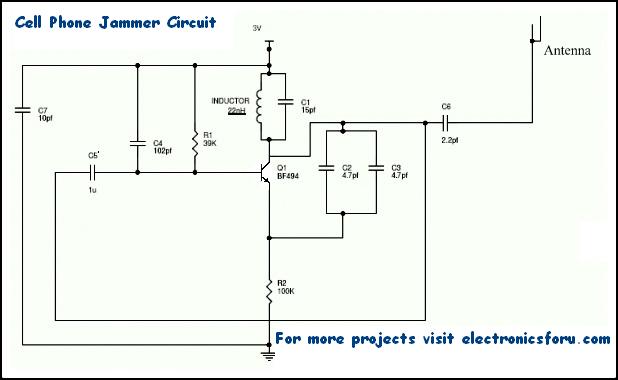
The RF amplifier stage is usually built around just one transistor, along with a few capacitors and resistors that keep it stable and efficient. Its job is simple: take the small oscillation coming out of the tuned circuit and boost it into a much stronger signal that the antenna can actually radiate. In a typical layout, Q1 handles the amplification, while C4, C5, and R1 take care of noise reduction, coupling, and emitter loading. Once the signal is amplified, it moves to the antenna through capacitor C6. That output coupling cap matters more than it might seem — it blocks DC and lets only the AC component pass, so the antenna sends out radio energy instead of leaking bias voltage from the power supply. There's also a timing detail worth pointing out: when Q1 turns on, the tuned circuit at the collector turns on with it. That tuned circuit, formed by capacitor C1 and inductor L1, acts like an oscillator with zero resistance, producing a very high frequency with minimal damping. The capacitor stores voltage, then discharges through the inductor once it's fully charged, and the inductor holds that energy as a magnetic field until it saturates and the whole cycle begins again.
Tuning is what gives you control over the whole thing. Change the inductor and capacitor values, and you move the output toward whatever band you're after — GSM 900, GSM 1800, or the 2.4 GHz and 5 GHz WiFi ranges. This is exactly why one block diagram can cover both a single-band phone jammer and a multi-band unit: the underlying architecture doesn't change, only the tuned values and how many parallel chains you stack.
How the Blocks Work Together to Jam a Signal
A jammer doesn't have to decode, listen in on, or even understand the traffic it disrupts. It just transmits low-power radio signals on the same frequencies a phone or WiFi device depends on, flooding the airwaves with competing energy. What happens next is interference between the handset and the base station: the phone keeps trying to communicate, but the receiver can't separate the legitimate signal from the noise anymore. This denial-of-service style interference is what shuts down calls, texts, and data inside the affected area. It's a brute-force approach rather than a clever one, and that's exactly why it works across so many protocols without any special knowledge of them. For the jammer to succeed, its power signal at the receiver has to be equal to or higher than the incoming signal power, which is why even a modest transmitter can silence a small zone.
The signal path here is intentionally linear: every stage feeds the next one, and nothing loops back. The oscillator is what actually creates the carrier wave in the first place. From there, the tuning circuit locks that carrier onto the target frequency, so it ends up sitting right where the phone or WiFi channel actually operates. Then the RF amplifier takes that low-power oscillation and boosts it to a level strong enough to be useful. Finally, the antenna radiates the amplified signal into the air. There's one detail in the amplifier stage that's worth pausing on. When the transistor turns on, the tuned circuit sitting at its collector turns on too. That tuned circuit acts like an oscillator with essentially zero resistance, so it rings at a very high frequency while losing almost no energy to damping. In other words, the amplifier stage isn't just adding gain — it's also contributing its own sustained oscillation, and that's part of why the output stays strong enough to interfere with the receiver.
For jamming to actually work, the interfering signal that reaches the receiver has to be at least as strong as the legitimate signal it's trying to drown out. That single power relationship explains more about real-world jamming than any clever circuit design does. Distance matters most—every meter between the jammer and the target device weakens the jamming signal, while the cell tower's signal keeps arriving at full strength. Walls and other obstacles pile on extra loss, and antenna gain on either side can tip the balance fast. That's why a weak jammer sitting next to a strong base station signal barely does anything, and why the same jammer works just fine in a basement or a shielded room. It also accounts for the range figures you see quoted for different designs, from roughly 100 meters for a mobile jammer circuit down to about 40 meters for a WiFi jammer, and as little as 30 square feet in some consumer setups. Bottom line: jamming is a contest of power at the receiver, not just a question of whether the oscillator is running.
Single-band jammers take a blunt but workable shortcut: they flood just one frequency, and that alone can be enough to fool a handset into thinking the network has vanished. Once the phone stops seeing a usable signal, it usually quits trying to register or transmit, which explains why even a basic design can be surprisingly effective in practice. Multi-band jammers, on the other hand, trade that simplicity for wider coverage. Rather than dumping all their output onto one slice of spectrum, they spread interference across several bands at once, so a phone hopping between frequencies has nowhere clean to land. That broader reach is exactly why multi-band jammer devices are typically described as portable units built to block multiple communication frequencies at the same time.
Key Components and Their Roles in the Circuit
For anyone actually building or repairing a jammer, the component-by-component breakdown found in published DIY tables is often the most useful part of the whole write-up. Instead of treating the circuit as a black box, these tables map each part to a specific job, which makes it much easier to swap in different values, trace a fault, or figure out why one stage of the circuit is misbehaving. In a typical transistor-based design, for example, the resistors handle emitter loading and base biasing, while the capacitors split into several roles: some generate or feed back frequency, others handle coupling and decoupling, and at least one is there to cut down noise. The transistor itself does the amplification, and the inductor works alongside a capacitor to set the frequency. Knowing this division of labor turns troubleshooting from guesswork into a logical process, since a dead oscillator, a weak amplifier, or a noisy supply can each be isolated and tested on its own. The table below summarizes the roles commonly assigned in a transistor-based jammer design.
| Component | Role in the Circuit |
|---|---|
| Resistor R1 | Emitter loading |
| Resistor R2 | Base biasing |
| Capacitor C1 | Frequency generation |
| Capacitor C2 | Feedback |
| Capacitor C3 | Feedback |
| Capacitor C4 | Noise reduction |
| Capacitor C5 | Coupling |
| Capacitor C6 | Coupling |
| Capacitor C7 | Decoupling |
| Transistor Q1 | Amplification |
| Inductor L1 | Frequency generation |
| Component | Role in the Circuit |
|---|---|
| Resistor R1 | Emitter loading |
| Resistor R2 | Base biasing |
| Capacitor C1 | Frequency generation with the inductor |
| Capacitors C2, C3 | Feedback |
| Capacitor C4 | Noise reduction |
| Capacitors C5, C6 | Coupling |
| Capacitor C7 | Decoupling |
| Transistor Q1 | Amplification |
| Inductor L1 | Frequency generation with the capacitor |
Reading the table as a signal path makes the design easier to follow. Bias resistors set the transistor operating point, feedback capacitors sustain oscillation, the LC pair sets the frequency, and coupling capacitors move the signal between stages while blocking DC. Decoupling and noise-reduction capacitors keep the supply clean so the oscillator does not drift.
A WiFi jammer design follows the same logic with a different target. It combines an RF amplifier to boost the generated signal, a noise circuit built from capacitors to generate broadband noise, and a tuning circuit using an inductor and capacitor to land on 2.4 GHz or 5 GHz. The noise stage is what differentiates it from a narrowband phone jammer.
Alternative approaches exist. A radio frequency jamming circuit built around a 555 timer is documented as a step-by-step project with its own schematic and component list. It is a different implementation of the same idea: generate a signal, tune it, amplify it, and radiate it. The block diagram survives even when the parts change.
Frequency Selection and Jamming Range
Frequency selection determines what a jammer can affect, and range determines how far that effect reaches. A mobile jammer circuit is described in published reports as able to block signals within a range of about 100 meters. A WiFi jammer design reports generating interference noise at the WiFi frequency and blocking the WiFi signal within roughly 40 meters. A consumer-facing explainer narrows the practical picture further, stating that jamming range is usually no more than about 30 square feet in real conditions.
Those numbers are not contradictory so much as context-dependent. Output power, antenna type, obstacles, and the strength of the target signal all shift the effective radius. A design tested on a bench with a nearby handset will look far more capable than the same circuit in a building with concrete walls and a strong carrier signal.
The governing rule remains the power relationship at the receiver. If the jammer signal arrives weaker than the legitimate signal, nothing happens. If it arrives at equal or greater power, communication fails. That is why published designs emphasize the RF amplifier stage: it is the block that decides whether the theoretical range survives contact with the real world.
For anyone comparing designs, the honest takeaway is that range claims should be treated as best-case laboratory figures unless the test conditions are described. Power supply quality, oscillator stability, and antenna matching matter as much as the headline number.
Single-Band vs Multi-Band Jammer Designs
Single-band jammers block one frequency range. They are simpler, cheaper, and easier to build, which makes them common in student projects and introductory DIY write-ups. Their weakness is coverage: a device that only targets one band leaves other services untouched, and its effectiveness depends entirely on whether the target device is using that band at that moment.
Multi-band jammer devices are described as portable units designed to block multiple communication frequencies at once. Dual-band designs specifically target GSM 900 and GSM 1800, covering two common cellular bands in a single enclosure. Architecturally, this usually means duplicating the oscillator, tuning, and amplifier chain for each band, then feeding a shared antenna network or separate antennas.
At the more advanced end, an intelligent jammer project detects unauthorized GSM signals in restricted areas and then jams those signals to prevent communication. Some intelligent jammers are described as able to communicate directly with the GSM provider to block services for specific clients. A 2025 paper on reactive jamming for long-term evolution uses a software-defined radio with custom processing blocks and a structured listening process, which shows how the block diagram concept carries into modern research.
The trade-off between the two approaches is straightforward. Single-band units are simpler and more predictable. Multi-band and reactive designs cover more ground but add cost, complexity, and interference risk, since broader output can affect services beyond the intended target.
Where Jammers Are Used and Why
Jammers are used to block wireless signals in areas that require wireless security, such as government offices and military installations. The technology was originally developed for military and law enforcement use, aimed at threats like cell phone-triggered explosives and hostage situations where an outside call could endanger an operation.
Proponents argue the same capability is needed in schools, theaters, vehicles, and quiet train cars, where talking, texting, and streaming may be disruptive or dangerous. In that framing, a jammer blocks incoming and outgoing phone calls, texts, and data transmission, and can also interfere with GPS, WiFi, and police radar.
The breadth of that interference is also the core objection. A jammer does not distinguish between a disruptive call and an emergency call. It simply raises the noise floor until communication fails, which means the same device that silences a classroom can also silence a 9-1-1 attempt.
That is why the use case debate is rarely settled by technical merit alone. The block diagram explains what the hardware does; it does not decide whether deploying it in a given place is wise or lawful.
Limitations, Detection, and Legal Risk
A signal jammer will interfere with a cell phone signal booster. Boosters amplify an existing signal, so if the incoming signal is being blocked, the booster has nothing useful to amplify. Signal amplifiers are therefore not an effective defense against jammers, despite being marketed as coverage solutions.
Detecting a jammer is difficult for average consumers. The most common symptom is dropped service, which looks identical to a network outage or a bad handset. Apps that claim to detect jammers are largely unproven and still require a working signal to function. Unless the jammer can be physically located and disabled, relocating may be the best practical option.
Legally, the picture is stark in the United States. It is illegal to sell, advertise, distribute, or operate cell signal jammers, and many other countries ban them as well. The FCC has stated that radio communication jamming equipment poses serious risks to critical public safety communications, can prevent 9-1-1 and other emergency calls, and can interfere with law enforcement communications.
Radio frequencies are protected by The Communications Act of 1934, which outlaws interference with authorized radio broadcasts. A Nigeria-based project report also notes practical limitations, including the fact that a given design may only block certain frequency bands and specific mobile carriers in that country. Understanding the block diagram is useful engineering knowledge; acting on it in most jurisdictions is not legal.
Frequently Asked Questions
What are the main blocks in a signal jammer block diagram?
Most jammer designs combine three subcircuits: an RF amplifier, a voltage controlled oscillator, and a tuning circuit. Some reports also list a power supply and antenna. The oscillator generates the interfering frequency, the tuning circuit sets it, and the RF amplifier boosts it before the antenna radiates it.
How does a cell phone signal jammer work?
A jammer transmits low-power radio signals on the same frequencies used by cell phones, creating interference between the handset and the base station. This denial-of-service style interference stops calls, texts, and data within range. Less sophisticated units jam only one frequency, which can make devices believe no signal exists.
Are cell phone signal jammers legal?
In the United States it is illegal to sell, advertise, distribute, or operate cell signal jammers, and many other countries also ban them. The FCC states jamming equipment interferes with authorized radio communications, can block 9-1-1 and emergency calls, and may interfere with law enforcement communications.
What range can a DIY mobile jammer cover?
Published DIY designs describe different ranges. One mobile jammer circuit is described as blocking signals within about 100 meters, while a WiFi jammer design reports blocking WiFi at 2.4 GHz or 5 GHz within roughly 40 meters. Actual range depends on power, antenna, and environment.