Sidelobe cancellation (SLC) uses small auxiliary antennas and adaptive weights to subtract jamming that enters a radar through its antenna sidelobes, restoring target detection when a standoff jammer is trying to bury the return. This guide walks through how the SLC loop works, how it differs from sidelobe blanking and adaptive beamforming, what limits cancellation to roughly 20-40 dB, and how pulse compression time sidelobes and CFAR interact with anti-jam protection.
What Is Sidelobe Cancellation and Why Does It Matter Under Active Jamming?
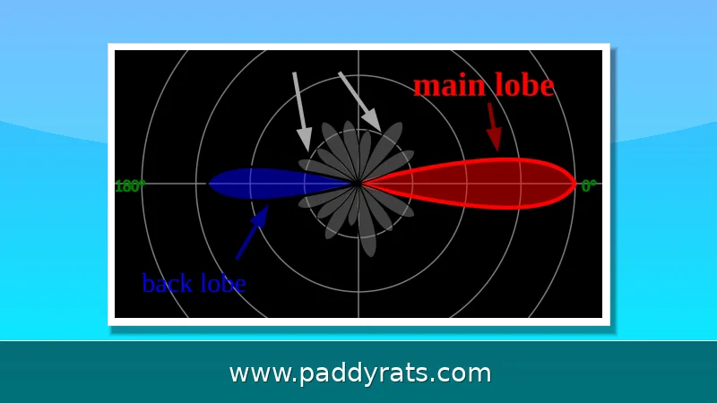
Active jamming almost never comes in through the main beam. Instead, think of a standoff jammer sitting off to the side of a rotating dish radar—most of its energy ends up pouring into the antenna's sidelobes, which usually run about 15 to 25 dB below the main lobe peak. That might sound like a lot of suppression, but it's still more than enough to bury a small target return. The reason comes down to how the two signals behave with range: radar echo power drops off as the fourth power of range, while jammer power drops off only as the square. So the jammer keeps the upper hand until the radar gets close enough to reach burn-through range, the point where the real echo finally rises above the interference.
Sidelobe cancellation (SLC) is the classic electronic counter-countermeasures (ECCM) fix for that geometry. The idea is to mount one or more small, low-gain auxiliary antennas around the main antenna, each with a gain roughly equal to—or a bit above—the main antenna's sidelobe level. That way, the auxiliary channel picks up basically the same jammer waveform the sidelobes are seeing, while capturing almost none of the target echo. The processor then subtracts a weighted copy of that auxiliary signal from the main channel, which drives the correlated jamming toward zero but leaves the uncorrelated target more or less untouched.
How the SLC Loop Works: Auxiliary Antennas, Adaptive Weights, and Null Steering
At its heart, the computation is just a subtraction with adaptive coefficients: y_output = x_main - sum(w_k * x_aux_k). But the weights w_k aren't hardwired. They're derived by minimizing the total output power while holding the main beam gain steady, which nudges the weights toward cancelling anything correlated between the main and auxiliary channels. The jammer shows up strongly correlated across those channels, while the target echo doesn't, so the loop settles onto the jammer and pretty much ignores the target. In spatial terms, what you get is a steerable null that automatically aims itself at the jamming source.
The original setup relied on a single control loop that steered one null against one jammer. Each auxiliary antenna you add buys you the ability to cancel one more independent jammer source, which is why most installations carry two to four auxiliary channels. Later work turned this into a more general problem, leading to optimal adaptive algorithms like Minimum Variance Distortionless Response (MVDR)—the same math that sits underneath modern adaptive arrays. As for who gets credit: Paul Howells is generally recognized as the inventor of the sidelobe canceller (US Patent 3,202,990), while Sid Applebaum is credited with the mathematical analysis and its extension to adaptive arrays. Both men worked at General Electric's Heavy Military Electronics Department in Syracuse, which later became the Special Projects Lab of SURC (Syracuse University Research Corporation, now SRC). Sidelobe cancellation itself has been deployed on military radars since the 1960s.
Sidelobe Cancellation vs Sidelobe Blanking vs Adaptive Beamforming
People tend to lump these three techniques together, but they actually solve different problems. Sidelobe blanking (SLB) compares the main antenna channel with a broader auxiliary channel and throws out any signal that looks stronger outside the main beam. Its job is to defeat false-target jamming, not to dig out a real echo that's buried in noise. SLC works differently: it leaves the main antenna pattern untouched and focuses on canceling jamming, which is exactly why it can be retrofitted onto older rotating dish radars that lack element-level digital receivers. Adaptive beamforming is the most ambitious of the three. It uses the entire array, so it can reshape the main beam itself, but that flexibility comes at a cost, since it needs a phased array with per-element digital receivers.
One way to keep them straight is to compare what each one actually changes and what it costs you.
| Technique | Primary target | Hardware requirement | Effect on main beam |
|---|---|---|---|
| Sidelobe cancellation (SLC) | Cancels sidelobe jamming | 2-4 low-gain auxiliary antennas | None; main pattern stays fixed |
| Sidelobe blanking (SLB) | Rejects false targets from sidelobes | One broad auxiliary channel | None; blanks the pulse instead |
| Adaptive beamforming | Nulls jammers anywhere, including main beam | Full phased array with element-level digital receivers | Can reshape or distort the main beam |
Patent US6538597B1 tells you a lot about how these pieces actually fit together. Raytheon filed it in 2000, and it was granted in 2003. The setup it describes works like this: once sidelobe jamming shows up, the canceler plants a null in the jammer's direction, and the blanker gets switched off. Meanwhile, an open-loop nulling circuit puts nulls in both the main beam and the blanker beam, and it does this with a pair of orthogonal linear arrays — one omnidirectional in azimuth and directional in elevation, the other doing the opposite. The patent lapsed in 2020, and that's part of why you now see this architecture discussed so freely in the open literature.
Performance Limits: Cancellation Ratio, Pattern Mismatch, Bandwidth, and Multipath
The cancellation ratio—how much you improve the signal-to-jammer ratio—usually lands somewhere between 20 and 40 dB. Real-world numbers tend to sit at the lower end of that range, though, and the biggest reason is auxiliary antenna pattern mismatch. If the auxiliary pattern doesn't closely track the shape of the main antenna's sidelobes, the two channels end up seeing slightly different versions of the jammer, and cancellation levels off at around 25 to 35 dB. Bandwidth mismatch is the other main culprit. When the jammer's bandwidth exceeds that of the cancellation loop, performance drops off at frequencies away from the loop center, which means a wideband noise jammer is considerably harder to cancel than a narrowband one.
Two more effects put a ceiling on how well any of this works. First, the auxiliary receiver's own internal noise sets a cancellation floor — once the subtracted jamming signal drops below that noise level, there's simply nothing left to gain. Multipath is the other culprit: when jamming reaches the radar along several paths with different delays, a single-tap cancellation weight can't account for all of them, so whatever isn't cancelled leaks through as residual interference. Taken together, these limits are why SLC functions as a mitigation rather than a cure, and why it usually gets paired with frequency agility, waveform diversity, and solid operator training instead of being trusted on its own.
Sidelobe Cancellation in Pulse Processing: Pulse Compression, Time Sidelobes, and CFAR
Pulse compression, most commonly a linear frequency modulated chirp, improves range resolution and effective range for a given peak output power. The price is that the compressed pulse is accompanied by sin(x)/x time sidelobes, also called range sidelobes. They arise when the ideal radar return is convolved with a less-than-ideal correlation filter response, or when a non-ideal return meets a less-than-ideal filter, spreading energy in range. Ground clutter and transmit anomalies make this worse, because strong nearby returns leak into range cells where a weak target is hiding.
Windowing, or amplitude weighting, reduces time sidelobes but costs signal-to-noise ratio. The classic numbers show the trade: a rectangular window with no weighting has a theoretical time sidelobe level of -13.2 dB, while a Hamming window reaches -42.8 dB. Sidelobe level is normally measured by illuminating a reference target and measuring at the pulse compression filter output. A Vector Signal Analyzer can act as an ideal radar pulse compression receiver for transmitter-only measurements, in much the same way error vector magnitude is measured on a communications transmitter; Agilent 89600 VSA software or MATLAB can perform the correlation filter function.
Detection logic has to keep working through all of this. Interference is a key factor in radar return misdetection, and the design goal is minimal false alarm probability with high detection probability, which is what constant false alarm rate (CFAR) processing provides. One published approach modified the Maisel SLC algorithm into a new algorithm for target recognition under severe interference, simulating received returns and interference as non-stationary and cancelling sidelobe interference adaptively; the simulation results showed a considerable increase in target recognition and signal-to-noise ratio versus the previous technique in severe clutter. CFAR SLC keeps the decision threshold and false alarm probability constant even when input SNR varies, which is what makes the whole chain usable in a real jamming environment.
Deployment, History, and Practical Design Considerations
SLC has been fielded on military radars since the 1960s, and the design trade space has stayed remarkably stable. The engineer's checklist is short but unforgiving: enough auxiliary channels to cover the expected number of independent jammers, auxiliary patterns that track the main antenna's sidelobes closely across the band of interest, a cancellation loop bandwidth matched to the jammer, and an auxiliary receiver noise floor low enough that it does not become the limiting factor. Get any of those wrong and the cancellation ratio collapses toward the 25 to 35 dB pattern-mismatch ceiling rather than the 20 to 40 dB headline figure.
It also helps to be honest about the boundary of the technique. SLC cancels sidelobe jamming only. Under main beam jamming the jammer is far stronger in the main channel than in the auxiliary channels, so subtracting it would cancel the target along with it; that scenario calls for adaptive beamforming, sidelobe blanking, or simply waiting for burn-through range. First-hand accounts of the early work, including material contributed by Dean Chapman to the Engineering and Technology History Wiki, and course instruction from Chuck Quintero at the Johns Hopkins University Applied Physics Laboratory, both stress the same point: SLC is one layer in a layered ECCM architecture, not a standalone answer to electronic attack.
How Does Sidelobe Cancellation Work in Radar Anti-Jam Protection?
SLC places small low-gain auxiliary antennas around the main antenna, each with gain near the main antenna's sidelobe level, so the auxiliary samples the jammer but almost none of the target echo. The processor computes adaptive weights and subtracts the auxiliary signals from the main signal, cancelling the correlated jamming while preserving the uncorrelated target. The result is an automatically steered null aimed at the jammer, with the main antenna pattern left unchanged.
What Limits Sidelobe Cancellation Performance?
Cancellation ratio is typically 20 to 40 dB, but the practical ceiling is usually set by auxiliary antenna pattern mismatch, which often holds cancellation to 25 to 35 dB. Bandwidth mismatch between the jammer and the cancellation loop degrades performance at frequency offsets, the internal noise of the auxiliary receiver sets a cancellation floor, and multipath with different delays defeats single-tap cancellation. These are the four limits worth checking first in any SLC design review.
Can Sidelobe Cancellation Protect Against Main Beam Jamming?
No. SLC cancels sidelobe jamming only. In main beam jamming the jammer is much stronger in the main channel than in the auxiliary channels, so subtracting it would also cancel the target. Main beam jamming needs adaptive beamforming, sidelobe blanking, or burn-through instead. Treating SLC as a main beam solution is one of the most common misunderstandings of how the technique is actually deployed.
How Is SLC Different From Adaptive Beamforming?
SLC uses a small number of auxiliary antennas, typically two to four, to cancel specific jammers while the main antenna pattern stays fixed, so it can be retrofitted to legacy rotating dish radars. Adaptive beamforming uses the full array with element-level digital receivers and can affect the main beam shape. SLC is cheaper and easier to add to existing hardware; adaptive beamforming is more capable but demands a phased array from the start.
Frequently Asked Questions
How does sidelobe cancellation work in radar anti-jam protection?
SLC places small low-gain auxiliary antennas around the main antenna. Each auxiliary has gain near the main antenna's sidelobe level, so it samples the jammer but not the target echo. The processor computes adaptive weights and subtracts the auxiliary signals from the main signal, cancelling correlated jamming while preserving the target.
What limits sidelobe cancellation performance?
Cancellation ratio is typically 20-40 dB, limited by auxiliary antenna pattern mismatch (often 25-35 dB), bandwidth mismatch between jammer and cancellation loop, internal noise of the auxiliary receiver, and multipath where single-tap cancellation is insufficient.
Can sidelobe cancellation protect against main beam jamming?
No. SLC cancels sidelobe jamming only. In main beam jamming the jammer is much stronger in the main channel than in auxiliary channels, so subtracting it would also cancel the target. Main beam jamming needs adaptive beamforming, sidelobe blanking, or burn-through instead.
How is SLC different from adaptive beamforming?
SLC uses a small number of auxiliary antennas (2-4) to cancel specific jammers while the main antenna pattern stays fixed, so it can be retrofitted to legacy rotating dish radars. Adaptive beamforming uses the full array with element-level digital receivers and can affect the main beam shape.