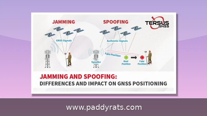
A hands-on look at how DIY signal jammers work, from NE555 and ESP32 builds to flyback coil tuning, plus why the FCC says you cannot legally build or use one in the US.
What Is a Signal Jammer and How Does It Work?
A signal jammer is basically a transmitter that drowns out other radios by blasting strong interference onto the same frequency they're using. With cell phones, it cuts the link between the handset and the base station, so the phone can't register, ring, or hold a call. Builders say these devices work against UMTS, 3G, CDMA, GSM, and PHS networks — which is why the same basic design keeps popping up in everything from pocket-sized phone blockers to drone and Wi-Fi jammers.
The basic idea is pretty straightforward: you tune into the same frequency the target uses, then flood it with noise. A simple jammer circuit like this can disrupt a wide range of RF signals over roughly 5 to 10 meters, and a well-built RF jamming device can cover anywhere from 50 MHz to 1 GHz. One documented build used 450 MHz as its tuning frequency, and jammers for other bands follow essentially the same design approach. That said, if you push a circuit too far beyond what it was built for, stability becomes a real problem. Take a design tuned for higher bands and try to make it jam starting at 500 MHz — it may start to drift or cut out altogether.
Core Subcircuits: RF Amplifier, VCO, and Tuning Circuit
Any working design really boils down to three subcircuits: an RF amplifier, a voltage controlled oscillator, and a tuning circuit. The amplifier stage centers on transistor Q1, along with capacitors C4 and C5 and resistor R1. Its job is to take the weak signal coming out of the tuned circuit, boost it, and feed it through C6 to the antenna. That capacitor isn't just there for show, either—it blocks DC while letting AC pass, which keeps the supply voltage from reaching the antenna feed.
A tuned circuit made from capacitor C1 and inductor L1 behaves like an oscillator with essentially zero resistance, generating a high frequency with very little damping. The energy keeps bouncing back and forth: it builds up as voltage in the capacitor, then discharges through the inductor, which stores it as magnetic energy, and the whole cycle starts over again. If you'd rather watch this principle play out on something modern and cheap, an ESP32 paired with dual NRF24L01 modules can show you Bluetooth communication, 2.4GHz interference, and real-world RF behavior up close before you commit to an analog build.
Building a Cell Phone Jammer with Basic Components
A basic cell phone jammer build starts with the driver circuit. Wind the primary and secondary coils the same way, then install a fast diode to protect the transistor from voltage surges and drops. Use a large heatsink here, and when it comes to the flyback primary and secondary, go with screws instead of solder—that way you can adjust and re-seat the windings without damaging them.
Flyback prep is where most first-timers mess up. You'll want to make a stiff paper cylinder, glue the coils in place, and set the ferrite cores correctly with plastic plates sandwiched between them to cut down on ultrasound vibrations. Soak the coil in paraffin wax first, though epoxy holds up better against melting than paraffin does. From there, move on to the antenna: longer antennas give you more range, but you'll likely pick up MW noise at longer distances, and VHF noise tends to show up most around 8–10 meters. Adding secondary coils is another way to stretch the range and get more out of the driver.
A lot of hobbyists go the shortcut route: buy a cheap portable cell phone jammer and modify it. The point of the mod is to shift it off the Chinese frequencies it was built for and onto American or other regional bands. Still, don't expect a free lunch. The trade-offs are real. Drop in a small heatsink and the transistor starts heating up within a short period, so you'll need a large one instead. And if you push for higher secondary wattage, that calls for a different secondary altogether—plus the secondary voltage may end up being too much for the primary coil to handle.
The table below breaks down the main components you'll find in a typical build and explains what each one actually does.
RF Jammer Coil, Antenna, and Resonance Tuning Steps
Coil and antenna specs are where a build stops being theoretical and starts getting real. A typical coil runs 1mm thick with 0.1 mm magnet wire, and the secondary puts out 8–9 mm sparks, which means you'll need a 20W power supply to drive it. A store-bought jammer paired with a 2-meter antenna reaches about 10–15 meters, and in one test the spark gap jumped from 2–3 mm to roughly 8 mm once the antenna was hooked up.
Resonance tuning is really the make-or-break step here — get it wrong and the whole thing just won't work. Hook up a 0-10V DC voltmeter, then turn the 22p trimmer until you see a maximum reading of 3V, and from there fine-tune it back down to the frequency you actually want. An ideal RF jamming device would use 22pF trimmers and cover the whole 50 MHz to 1 GHz range, though if you try to force it to jam starting at 500 MHz, you'll likely run into stability problems.
Keep this checklist handy while you're tuning — it'll save you a lot of guesswork once things start drifting.
DIY Wi-Fi and Bluetooth Jammers Using ESP32 and NRF24L01
The modern DIY scene has largely moved to microcontrollers. An ESP32 with dual NRF24L01 modules is the standard demonstration platform for Bluetooth and 2.4GHz interference, and it is cheap enough that a failed experiment costs little. Other projects use an ESP8266 for a portable Wi-Fi jammer or deauther, while the ESP32-BlueJammer covers Bluetooth, BLE, Wi-Fi, and RC signals in one board.
These builds are popular because they are easy to source and easy to reflash, but the same 2.4GHz band carries Wi-Fi, Bluetooth, and many RC links, so a single board can affect far more than its owner intends. That overlap is exactly why regulators treat them the same as any other jammer, regardless of how the project is labeled.
The table below compares the common DIY platforms and what they target.
Frequency Ranges, Range Limits, and Stability Trade-offs
Range claims deserve skepticism. A simple jammer circuit can jam a wide range of RF signals between 5 and 10 meters, and an ideal RF jamming device covers 50 MHz to 1 GHz. A pre-made jammer with a 2-meter antenna operates at 10-15 meters. Those numbers assume a clean build, a matched antenna, and a power supply that can actually deliver the current the coils demand, such as the 20W supply needed for 8-9 mm sparks.
Stability is the hidden cost. Forcing a device tuned for higher bands to jam from 500 MHz may cause instability, and a small heatsink causes transistor heating within a short period. Paraffin wax melts more easily than epoxy, and higher secondary wattage requires a different secondary because secondary voltage may be too much for the primary coil. Each of these trade-offs shortens usable runtime or narrows the effective band.
One published paper recommends further and deeper research to produce more sophisticated jamming devices that do not affect other services, which is a fair summary of how crude most hobby builds remain.
Is It Legal to Build or Use a Signal Jammer in the US?
No. The FCC states that federal law prohibits operating, marketing, or selling any jamming equipment, including devices that interfere with authorized radio communications such as cell phones, GPS, police radar, and Wi-Fi. Consumers cannot legally use jammers in the United States, and retailers cannot lawfully sell them either. The agency maintains a dedicated jammer enforcement page and has pursued sellers and operators for years.
The rules are not limited to the US. A jammer may be illegal where you are because of public safety concerns, since blocking calls can interfere with emergency communications. Even academic projects run into this: a GSM jammer project was documented as only blocking certain frequency bands and mobile carriers in Nigeria, which is a reminder that legality and effectiveness both vary by region and by band.
Common Questions from Builders and Forum Users
Forum users repeatedly ask for tutorials to create their own cell phone signal jammer, and viewers ask whether a circuit can be built for 4G and 5G mobile network bands with a range of about 5 meters. The honest answer is that the analog approach scales poorly to modern bands, which use wider channels and more complex modulation than the GSM designs most tutorials target.
One commenter made a pointed observation: calling it a wireless module for Arduino would be perfectly legal and just as much of a jammer. That captures the gap between labeling and effect. Recent activity in the space includes a DIY Bluetooth jammer using ESP32 and NRF24L01 posted about five months ago, a DIY BLE/Wi-Fi jammer Reddit thread from about a year ago, a DIY RF jammer PCB guide, an FCC jammer enforcement page updated eight days ago, and a 2025 paper on reactive jamming attacks against LoRaWAN.
For anyone weighing a build, the practical takeaway is that the electronics are well documented and the legal exposure is not worth it. Study the RF theory, practice with a spectrum analyzer and a receive-only setup, and keep the transmitter off the air.
How to Make a Signal Jammer: DIY RF, Wi-Fi and Cell Phone Circuits
| Component | Role | Typical Spec |
|---|---|---|
| RF amplifier (Q1, C4, C5, R1) | Boosts tuned signal to antenna | Passes AC through C6, blocks DC |
| Tuned circuit (C1, L1) | Oscillator at target frequency | Near-zero resistance, minimal damping |
| 22pF trimmer | Resonance adjustment | Peak reading 3V on 0-10V DC voltmeter |
| Flyback coil | Generates high voltage | 1mm thickness, 0.1 mm magnetic wire |
| Power supply | Drives secondary | 20W for 8-9 mm sparks |
| Platform | Targets | Notes |
|---|---|---|
| ESP32 + dual NRF24L01 | Bluetooth, 2.4GHz | Common demo platform |
| ESP8266 | Wi-Fi, deauther | Portable builds |
| ESP32-BlueJammer | Bluetooth, BLE, Wi-Fi, RC | Single-board coverage |
Frequently Asked Questions
Is it legal to build or use a signal jammer?
In the United States, federal law prohibits operating, marketing, or selling any jamming equipment that interferes with authorized radio communications such as cell phones, GPS, police radar, and Wi-Fi. The FCC warns that consumers cannot legally use jammers, and retailers cannot lawfully sell them. Building one for personal use carries the same risk as buying one.
What are the main parts of a cell phone jammer circuit?
A cell phone jammer needs three subcircuits: an RF amplifier, a voltage controlled oscillator, and a tuning circuit. Together they generate interference on the same frequency as a mobile handset, blocking communication between the phone and the base station. The RF amplifier uses a transistor with supporting capacitors and a resistor, while the tuned circuit uses a capacitor and inductor as the oscillator.
What frequency range can a simple RF jammer cover?
A simple jammer circuit can jam a wide range of radio frequency signals between 5 and 10 meters. An ideal RF jamming device should cover 50 MHz to 1 GHz, though forcing it to jam signals from a 500 MHz range may cause stability issues. Longer antennas extend range, but MW noise appears at longer distances while VHF noise is most prevalent at 8-10 meters.
Which components are used in a DIY Wi-Fi or Bluetooth jammer?
DIY builds commonly use an ESP32 with dual NRF24L01 modules to demonstrate Bluetooth and 2.4GHz interference. Other projects use an ESP8266 for a portable Wi-Fi jammer or deauther, and the ESP32-BlueJammer covers Bluetooth, BLE, Wi-Fi, and RC signals. Because these bands overlap with Wi-Fi and RC links, regulators treat them as jammers regardless of how the project is labeled.