A practical walkthrough of DIY RF jammer circuits, from the RF amplifier and VCO to coil specs and antenna range, plus the FCC rules that make building one illegal in the US.
What Is a Signal Jammer and How Does It Work?
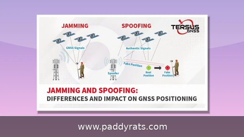
A signal jammer is basically a transmitter that floods one part of the radio spectrum with enough noise to bury the legitimate signals sitting on top of it. In a cell phone jammer, the device broadcasts right on the frequencies the handset uses to reach the base station, so instead of hearing the tower's control channel, the phone just hears interference and drops the connection. The same logic holds for GPS at 1575MHz and WiFi at 2.4GHz and 5GHz — the noise floor climbs until the receiver can't pull the original transmission out anymore.
Most jammers work on a principle called noise jamming: the device just blasts RF noise on the same frequencies your phone and the tower are trying to talk on, so the original signal gets drowned out and the connection falls apart. Fancier hardware goes a different route, using protocol jamming to hit the control channels head-on instead of blanketing a whole band. Either way, that barrier is never permanent — it only exists while the jammer is transmitting, and only within its effective radius. How big that radius is depends a lot on the build. A simple circuit thrown together around a 555 timer or a flyback driver will usually jam RF signals somewhere in the 5 to 10 meter range, which is fine for a small room and not much else. Off-the-shelf commercial units tend to do better, often reaching 10 to 15 meters, thanks to cleaner amplification and better-tuned antennas.
| Jammer Type | Typical Effective Range | Notes |
|---|---|---|
| Simple DIY circuit (555 timer or flyback driver) | 5–10 meters | Good for small rooms; range varies with tuning and antenna |
| Pre-made commercial unit | 10–15 meters | Better amplification and antenna design |
Before we go any further, let's be clear about what this is: an educational look at how these circuits actually work, not a build guide you can legally put into service. In the United States, the FCC is blunt about it — operating, marketing, or selling jammers violates federal law, and that ban isn't just about cell phones. It covers any device designed to intentionally block, jam, or interfere with authorized radio communications, whether that's police radar, GPS, or WiFi. Retailers can't legally sell them either, and plenty of other countries take a similarly hard line. So read the technical discussion that follows as theory and experimentation only — not as permission to flip a switch.
Core Subcircuits: RF Amplifier, VCO, and Tuning Circuit
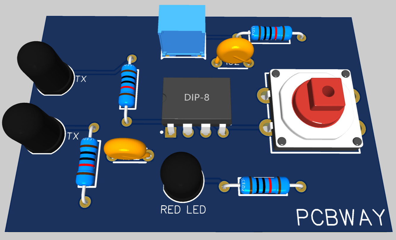
Any workable jammer design comes down to three main subcircuits: an RF amplifier, a voltage controlled oscillator (VCO), and a tuning circuit. The VCO is what generates the raw high-frequency carrier in the first place, the tuned circuit determines which frequency actually makes it through, and the RF amplifier takes that signal and boosts it up to a level the antenna can realistically radiate. You can't really skip any of these three, either — take one out and you're left with a circuit that either does nothing useful at all or puts out a signal so weak it might as well not be there.
In the classic transistor setup, Q1 does the heavy lifting as the amplifier, taking that weak oscillating signal and boosting it to a usable level. R1 handles the emitter loading, while R2 takes care of base biasing. Together they set the transistor's operating point, which is basically what decides how cleanly and consistently Q1 conducts. From there, C1 and inductor L1 form the tuned circuit at the collector. This LC pair acts like an oscillator with almost zero resistance, producing a high-frequency signal with very little damping, so the waveform holds up instead of dying out. C2 and C3 provide the positive feedback that keeps the oscillation going — they feed part of the output back to the input to keep the circuit ringing. The rest of the capacitors are there for housekeeping: C4 cuts down noise, C5 and C6 handle coupling between stages, and C7 decouples the supply rail so power-line ripple doesn't leak into the RF path. Get even one of these values wrong — a mismatched C1/L1 pair, for instance — and the circuit might drift off frequency or just refuse to oscillate at all.
| Component | Role in the Circuit |
|---|---|
| Q1 | Amplifies the oscillating signal |
| R1 | Emitter loading |
| R2 | Base biasing; sets operating point |
| C1 + L1 | Tuned circuit at collector; acts as oscillator with near-zero resistance |
| C2, C3 | Feedback that sustains oscillation |
| C4 | Noise reduction |
| C5, C6 | Coupling |
| C7 | Supply rail decoupling |
The amplified signal doesn't just shoot straight to the antenna—it has to go through the coupling stage first. Once Q1 boosts the RF waveform, that output leaves the collector and passes through capacitor C6 before it ever reaches the antenna. C6 pulls double duty: it blocks the DC bias voltage sitting on the collector while letting the AC radio-frequency signal pass through untouched. You can think of it as a gate that only opens for the part of the signal you actually want to radiate. That's important, because the transistor's bias voltage is only there to keep Q1 running in its linear region—it has no business leaking onto the antenna. If it does, you're basically feeding DC into a component built to radiate AC, which wastes power and can throw off the entire tuned circuit. Choose a coupling capacitor that's too small and you'll choke off the low-frequency output; go too large and you might pass unwanted DC or shift the response curve. Either way, the mistake shows up as weak range, or a circuit that looks fine on the bench but barely jams anything in real use. That's why coupling values deserve just as much attention as the coil and trimmer—skip that step, and even a perfectly wired build can fall flat.
Components Needed for a Basic Cell Phone Jammer
The parts list for a basic cell phone jammer circuit is short and cheap — which is probably why so many hobbyists end up giving it a shot. The core of the design is just one transistor doing the amplification, surrounded by a modest support crew: a few capacitors for coupling, feedback, noise reduction, and decoupling; a pair of resistors to set the biasing; and an inductor that forms the tuned circuit at the collector. When it comes to tuning, a 22pF trimmer capacitor is the usual pick, since it lets you adjust the resonant frequency by hand until the output sits where you want it. The coil is generally wound around a ferrite core, and builders often point out that the magnetic wire should be around 0.1 mm thick, with the coil itself measuring about 1 mm. Nothing here is exotic or pricey, and that's a big part of the appeal — though the same low barrier to entry is exactly why those legal warnings deserve attention.
| Component | Role in the Circuit | Typical Spec / Note |
|---|---|---|
| Transistor (Q1) | Amplification | Core active device |
| Capacitors (C1–C7) | Frequency generation, feedback, coupling, noise reduction, decoupling | Multiple small-value caps |
| Resistors (R1, R2) | Emitter loading and base biasing | Two resistors |
| Inductor (L1) | Tuned circuit / frequency generation | Wound on ferrite core; ~1 mm coil, ~0.1 mm magnetic wire |
| Trimmer Capacitor | Tuning | 22pF, standard choice |
When you get to the flyback section of the build, the coil specs get oddly precise, and messing them up can throw the whole circuit off. The coil itself should be about 1mm thick, and the magnetic wire wound around it is only 0.1mm — thin stuff, but still enough for the secondary coil to throw sparks in the 8 to 9mm range. Those sparks aren't free, though: keeping them going takes a 20W power supply, which is more than your average casual hobby build would draw. Since that much energy is running through the circuit, it's a good idea to drop in a fast diode to protect the transistor from voltage surges before it gets fried, and to bolt on a large heatsink so heat doesn't pile up while it's running. One more tip that keeps popping up in these designs: use screws instead of solder for the flyback connections, because soldered joints tend to give out under the heat this section puts out.
| Flyback Component | Specification |
|---|---|
| Coil thickness | 1mm |
| Magnetic wire gauge | 0.1mm |
| Secondary coil spark output | 8–9mm |
| Power supply | 20W |
| Protection | Fast diode to shield the transistor from voltage surges |
| Thermal management | Large heatsink |
| Connection method | Screws instead of solder for heat resistance |
The table below summarizes the roles of the main components in the oscillator section, based on the standard circuit description.
| Component | Function |
|---|---|
| Q1 | RF amplification of the tuned signal |
| R1 / R2 | Emitter loading and base biasing |
| C1 / L1 | Tuned circuit, frequency generation |
| C2 / C3 | Feedback to sustain oscillation |
| C4 | Noise reduction |
| C5 / C6 | Coupling, with C6 blocking DC to the antenna |
| C7 | Decoupling of the supply |
This is where the practical difficulty really shows up. A 22pF trimmer gives you only a narrow tuning window to work with, so there isn't much room to adjust before performance starts to drift. Pushing a design that was originally intended for 50 MHz to 1 GHz coverage down to 500 MHz or lower often introduces stability problems, and the circuit may become unpredictable or stop oscillating reliably. That is why most hobby builds stay narrowband and only block the carriers and bands they were specifically tuned for, rather than trying to cover everything at once. In practice, a modest, well-tuned circuit that reliably jams a handful of target frequencies tends to work far better than an ambitious wideband design that struggles to hold its center frequency.
Step-by-Step: Building an RF Jammer Circuit
The build starts with the driver circuit. Wind the primary and secondary coils the same way, install a fast diode to protect the transistor from voltage surges, and mount a large heatsink because these drivers run hot. Use screws instead of solder for the flyback connections; solder joints tend to fail under the thermal cycling this circuit sees.
Flyback preparation is the stage where a lot of builds succeed or fail, so take your time here. Start by creating a rigid paper cylinder to serve as the coil former, then connect the coils with glue so nothing shifts once the circuit starts vibrating. Place the ferrite cores correctly, with plastic plates sandwiched between them — this small detail matters more than it looks, because it cuts down the ultrasound vibrations that would otherwise produce an audible whine and waste energy. Next, presoak the coil in paraffin wax to hold the windings steady and suppress arcing. That said, if you expect the circuit to run hot, epoxy is the better choice, since paraffin will melt under sustained heat and leave your carefully wound coil loose.
Then bring in the antenna. Adding an antenna extends the spark length from 2 to 3mm up to roughly 8mm, and a 2-meter antenna pushes the effective range toward 10 to 15 meters. Secondary coils can extend range further. Finally, peak the resonance: attach a DC voltmeter in the 0 to 10V range between the test point and ground, adjust the 22p trimmer until you read a maximum of about 3V, then fine-tune to shift the output back to the proper frequency.
In practice, VHF noise from these builds is most prevalent at 8 to 10 meters, while medium-wave noise carries further. That asymmetry is a useful reminder that a jammer's real-world footprint depends on the band, the antenna, and the environment, not just the wattage on the label.
Tuning, Coil Specs, and Antenna Range
Tuning is the difference between a circuit that oscillates and one that jams anything. The peak resonance procedure is the key step: with a DC voltmeter connected between the test point and ground, you adjust the 22p trimmer for the highest reading, around 3V, which indicates the circuit is resonating efficiently. From there you fine-tune the trimmer to move the output back to the frequency you actually want to target.
Coil geometry is equally unforgiving. The main coil should measure 1mm in thickness and the magnetic wire 0.1mm, and the secondary coil in a flyback arrangement can generate 8 to 9mm sparks that require a 20W supply. Builders who deviate from these dimensions usually find the spark weak, the resonance unstable, or both.
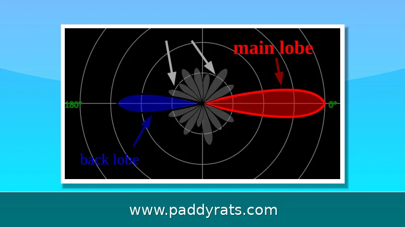
Antenna length is the last variable that changes range dramatically. A 2-meter antenna increases the spark length to about 8mm and supports a pre-made jammer operating at 10 to 15 meters. One documented project successfully blocked cell phone signals at 450MHz, which shows how tightly a narrowband design is tied to its target frequency. Push that same circuit to cover several bands and stability suffers.
Frequency Bands and Multiband Jamming
Signal jammers are defined by the bands they target. Cellular networks occupy 700MHz, 800MHz, 900MHz, 1800MHz, 1900MHz, and 2100MHz. GPS sits at 1575MHz, and WiFi uses 2.4GHz and 5GHz. A wide-band or multiband design, such as one covering 900 to 1900MHz, can hit GSM900, GPS, and GSM1800 at the same time, which is why those bands show up so often in commercial specs.
Ideal RF jamming equipment described in hobby sources uses 22pF trimmers and covers 50 MHz to 1 GHz, but forcing that same hardware to jam from 500 MHz upward introduces stability issues. The tradeoff is simple: the wider the coverage, the harder it is to keep the oscillator clean and the output predictable.
| Service | Frequency |
|---|---|
| Cellular (voice, SMS, data) | 700 / 800 / 900 / 1800 / 1900 / 2100 MHz |
| GPS | 1575 MHz |
| WiFi | 2.4 GHz and 5 GHz |
| Multiband coverage example | 900-1900 MHz (GSM900, GPS, GSM1800) |
Different form factors map to those bands. Portable signal jammers are handheld and battery-powered with short range, suited to small rooms or vehicles. Drone signal jammers use directional antennas against ISM bands and navigation signals to force a drone into failsafe hover or return. WiFi jammers block 2.4GHz and 5GHz to prevent wireless connections, and cell phone jammers target 700MHz to 2100MHz to block voice, SMS, and mobile internet.
Is It Legal to Build a Signal Jammer?
In the United States, no. The FCC warns that it is a violation of federal law to use, market, or sell cell jammers or similar devices that intentionally block, jam, or interfere with authorized radio communications such as cell phones, police radar, GPS, and WiFi. Consumers cannot legally use jammers, and retailers cannot lawfully sell them. Signal jamming is also illegal in many other countries.
The enforcement posture is not theoretical. The FCC maintains a dedicated jammer enforcement program, and importing, advertising, or shipping these devices into the US can trigger fines and seizure. That means the circuits described here are strictly for educational and experimental purposes on a bench, with a dummy load or shielded enclosure rather than an antenna broadcasting into the street.
There are also real-world limitations even if you ignore the law. One project documented that its build only blocked certain frequency bands and mobile carriers in Nigeria, and RF jammer designs are frequently incompatible with other frequencies. Producing a more sophisticated jamming device without affecting other communications requires further research, not just a bigger amplifier.
Countermeasures and Detection
Because jamming is a blunt instrument, the defenses against it are well understood. Variable frequencies and frequency hopping capability let a transmitter move away from the jammed channel faster than a noise source can follow, which is why spread-spectrum techniques are standard in modern radios. A jammer that blankets a fixed band is far easier to escape than one that tracks its target.
Detection is the other half of the equation. Jammer detectors can be built to flag elevated noise floors in specific bands, and cell phones could incorporate GPS jam-to-noise (J/N) ratio detectors to identify interference and help localize its source. In practice, a rising J/N ratio is one of the clearest early indicators that something nearby is transmitting on top of a satellite signal.
For anyone studying RF security, the useful takeaway is that jamming and anti-jamming are a matched pair. Understanding how a simple oscillator plus amplifier can raise the noise floor is the same knowledge you need to design a receiver that notices when it happens. That is the legitimate, legal use of this material.
Frequently Asked Questions
How does a signal jammer actually block signals?
A jammer transmits radio frequency noise on the same frequencies used by phones, GPS, or WiFi. That noise overpowers the original signals from towers and satellites, creating a barrier that stops devices from sending or receiving transmissions. Wide-band models block several frequency bands at once, while narrowband designs only disrupt the specific band they are tuned to.
What are the three main subcircuits in a cell phone jammer?
Any jammer circuit needs an RF amplifier, a voltage controlled oscillator, and a tuning circuit. Together these form an efficient cell phone jammer. The RF amplifier boosts the tuned signal, and the antenna transmits it after a coupling capacitor blocks DC so the transistor bias never reaches the antenna.
Is building or using a signal jammer legal?
In the United States, federal law prohibits operating, marketing, or selling any jamming equipment, including devices that interfere with authorized radio communications such as cell phones, police radar, GPS, and WiFi. Consumers cannot legally use jammers, and retailers cannot lawfully sell them. Signal jamming is also illegal in many other countries, so treat these circuits as educational only.
What frequency bands do signal jammers target?
Common targets include cellular bands at 700MHz, 800MHz, 900MHz, 1800MHz, 1900MHz, and 2100MHz, GPS at 1575MHz, and WiFi at 2.4GHz and 5GHz. A multiband design may cover 900-1900MHz for GSM900, GPS, and GSM1800, though widening coverage often introduces oscillator stability problems.