A practical walkthrough of DIY RF, WiFi and cell phone jammer circuits — the subcircuits that matter, the parts you need, and the federal law that makes building one for real-world use a serious problem.
What Is a Signal Jammer and How Does It Work?
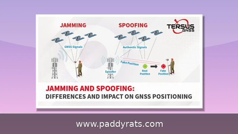
A signal jammer is basically a transmitter that drowns out a specific frequency band with RF noise, so any receiver nearby can't separate the real signal from all that static. The idea itself isn't complicated: noise jamming simply overpowers whatever is coming from a cell tower, GPS satellite, or WiFi access point, which effectively builds an invisible wall between your device and the network it's trying to reach. Fancier setups take a different route with protocol jamming, going after the control channels devices rely on to set up a connection instead of just cranking up the noise floor.
A homemade circuit won't get you much range. Most simple jammers only cover about 5 to 10 meters, though a well-tuned build with 22pF trimmers that spans 50 MHz to 1 GHz does noticeably better. Try to stretch that same design across a 500 MHz span, though, and you're asking for trouble—the oscillators drift, harmonics wander, and the output turns unreliable. Off-the-shelf units are usually rated for 10 to 15 meters, and antenna length plays a real role here: with a 2-meter antenna, the spark length in a flyback-driven build jumps from 2–3 mm to around 8 mm.
Noise doesn't behave the same way across the whole spectrum—it changes depending on both distance and band. VHF noise is usually at its worst around 8–10 meters, whereas medium-wave noise doesn't really show up until you're farther away. That gap goes a long way toward explaining why multiband designs act so differently from single-band ones. Take a 900–1900 MHz project that has to cover GSM900, GPS, and GSM1800 at the same time: juggling several bands at once means its range and stability will never quite match a jammer tuned to a single frequency. Commercial cell phone jammers follow that same multiband logic, blocking UMTS, 3G, CDMA, GSM, and PHS all together. And the frequency list they go after is pretty standard by now: cellular at 700/800/900/1800/1900/2100 MHz, GPS at 1575 MHz, and WiFi at 2.4 GHz and 5 GHz.
Core Subcircuits: RF Amplifier, VCO and Tuning Circuit
Take away the case, the antennas, and the battery pack, and what's left of any jammer—a handheld signal blocker or a wide-band multiband unit—comes down to the same three building blocks: an RF amplifier, a voltage controlled oscillator (VCO), and a tuning circuit. You can think of the VCO as the voice, the tuning circuit as the pitch control, and the RF amplifier as the megaphone that makes the noise loud enough to actually matter in the air. The amplifier takes that weak, tuned oscillation and pushes it up to a power level that can radiate from the antenna with enough strength to drown out nearby cell towers or GPS satellites. In a typical schematic, that job falls to transistor Q1, working alongside capacitors C4 and C5 and resistor R1 to set gain and stabilize the stage. From there, the boosted signal travels to the antenna through C6, a coupling capacitor that does double duty: it blocks DC voltage from the supply while letting the AC radio signal pass through untouched. Get these three stages right, and the rest of the build—driver circuits, flyback transformers, antennas—has something solid to work with.
The oscillator is pretty much the heart of the whole build — everything else is just there to feed it, amplify it, or point it somewhere. A tuned circuit made from capacitor C1 and inductor L1 acts as an oscillator with basically zero resistance, so it rings at a high frequency with very little damping and holds a clean, steady tone. The tuning circuit is what decides which band that oscillator actually lands on, and that's where the 22pF trimmer comes in. Think of it as a fine-adjustment knob: change its capacitance a little and you shift the resonant point of the LC pair, sliding the output up or down the spectrum. To find peak resonance, hook up a 0–10V DC voltmeter across the circuit and turn the 22p trimmer until the reading maxes out at around 3V. That peak tells you the tank is resonating efficiently, but it's not always the frequency you're after. From there, back the trimmer off slightly and fine-tune until the circuit settles on the right frequency for your target band. It's a small, fussy step, but skip it and you'll usually end up with a jammer that hums along just fine while missing the band it was built for.
| Stage | Component | What It Does | Adjustment / Target |
|---|---|---|---|
| Oscillator | C1 + L1 tuned circuit | Generates the high-frequency signal with near-zero resistance and minimum damping | Sets the base oscillation |
| Tuning | 22pF trimmer | Shifts the resonant point to select the band | Fine-tune to the desired frequency |
| Peak resonance check | 0–10V DC voltmeter | Confirms the tank is resonating efficiently | Adjust trimmer to max ~3V, then tune back |
Terminology actually matters a lot once you start hunting for parts and schematics, since the same basic idea goes by a bunch of different names: RF jammer, signal blocker, GPS jammer, text stopper, noise jamming, protocol jamming, full spectrum jammer, wide-band jammer and multiband jammer. Figuring out which term a particular project page uses can save you serious time, because a wide-band jammer guide and a single-band GPS jammer guide are describing very different circuits, even if the physics underneath them works the same way.
Building a Simple Cell Phone Jammer with a 555 Timer or NE555
If you've ever pulled up a beginner-friendly cell phone jammer schematic, there's a good chance a 555 timer was sitting right in the middle of it. The NE555 version especially pops up in most of the widely shared designs, and honestly, that makes sense — it's cheap, easy to get your hands on, and predictable enough for someone who's never built an oscillator before. In this kind of circuit, the timer handles the heavy lifting by generating the oscillation, while the tuned network — usually just a small mix of inductors and capacitors — determines which band actually gets targeted. From there, a modest amplifier stage boosts the signal and feeds it to the antenna. Take the well-known build from ElectronicsForU: it uses 450 MHz as its tuning frequency. The real takeaway from that project is that other frequency ranges are designed in exactly the same way. You swap out the LC values to shift the circuit to a different band, but the underlying architecture stays the same.
Coil winding is where most first builds fall apart, so don't treat it like an afterthought — this step makes or breaks the whole thing. You're aiming for about 1 mm thickness with 0.1 mm magnetic wire, and keep in mind that the secondary winding needs to throw 8–9 mm sparks, which means a 20W power supply to sustain that kind of output. Wind the primary and secondary the same way so the coupling stays predictable, then drop in a fast diode to protect the transistor from voltage surges. A big heatsink isn't optional here, either; these circuits run hot, and skipping it is basically inviting thermal failure. For the flyback coils, use screws instead of solder — solder joints crack under heat and vibration. Make a stiff paper cylinder and glue the coils to it so the geometry doesn't shift, and seat the ferrite cores properly with plastic plates between them. Nail these details and the circuit works beautifully; rush them and you'll be stuck debugging a dead board.
| Build Detail | Specification |
|---|---|
| Coil thickness | ~1 mm |
| Magnetic wire gauge | 0.1 mm |
| Secondary winding spark output | 8–9 mm |
| Power supply required | 20W |
| Flyback coil connection | Screws, not solder |
| Core spacing | Plastic plates between ferrite cores |
Those final steps are what make the difference between a circuit that only fires up on the bench and one that keeps working after it's been boxed up. First, presoak the coil in paraffin wax—this locks the windings in place and cuts down on vibration. In spots where you expect more heat, go with epoxy instead, since it handles melting better. Save the antenna for last so you're not fighting it while you tune, then add the secondary coils to stretch the effective range. And none of this requires anything exotic. The entire build comes down to a short, cheap list: a heatsink, a flyback driver, hard paper, glue, paraffin wax, 22pF trimmers, a transistor, an inductor, capacitors, and resistors. Odds are most of that is already rattling around in a typical hobbyist's parts bin, which is a big part of why this project stays doable for someone building their first one.
| Component | Specification | Role in the circuit |
|---|---|---|
| Coil wire | 1 mm thickness, 0.1 mm magnetic wire | Primary and secondary windings |
| Secondary output | 8-9 mm sparks, 20W supply | High-voltage drive for the flyback |
| Trimmer | 22pF | Tuning to peak resonance (~3V on a 0-10V meter) |
| Transistor | Q1 with C4, C5, R1 | RF amplification stage |
| Antenna | 2-meter length | Radiates the jamming signal |
DIY RF Jammer: Driver Circuit, Flyback and Antenna Steps
A DIY RF jammer build follows a predictable order, and skipping steps usually means starting over. Begin with the driver circuit and the tuned oscillator, confirm you can measure resonance with the voltmeter method, and only then move to the high-voltage section. The flyback transformer is the part that most often destroys a beginner's work, so treat the fast diode and the heatsink as mandatory rather than optional.
Mechanical assembly deserves as much attention as the electronics. Wind both coils in the same direction, glue them to a rigid paper cylinder, and insert the ferrite cores with plastic plates separating them. Screw terminals on the flyback coils let you disassemble and re-tune without desoldering, which matters because you will re-tune more than once. Presoaking the coil in paraffin wax reduces vibration, and epoxy adds heat resistance where the coil sits closest to the driver.
Once the antenna is attached, range testing is what tells you whether the tuning actually landed where you want it. Don't expect miracles from a basic circuit — a simple build typically covers somewhere between 5 and 10 meters, and the noise you hear won't be uniform across that span. VHF noise tends to be strongest at 8–10 meters, while MW noise only shows up farther out, so where you stand with your receiver matters as much as how you wound the coil. If you're working with a multiband design, say a 900–1900 MHz project covering GSM900, GPS, and GSM1800, each band needs its own tuned stage, and every stage has to be re-peaked individually — peak one, then go back and touch up the others, because adjustments interact. For written reference material on the RF side, WellPCB's guide was last modified on July 2, 2026, and it's still one of the more detailed walkthroughs available for this part of the build.
ESP32 and NRF24L01 Bluetooth and WiFi Jammer Builds
If you're new to RF experimentation and want a low-cost entry point, the ESP32 paired with an NRF24L01 module is widely considered the most accessible platform for tinkering with 2.4 GHz interference. The appeal comes down to how the work is divided: the ESP32 takes care of timing, logic, and overall control, while the NRF24L01 module handles the actual radio transmission. That division keeps the setup simple and the parts cheap, and it means the same hardware can be repurposed for BLE and WiFi research without buying anything new. Interest in this approach shows no sign of fading, either. A popular video walkthrough of an ESP32/NRF24L01 Bluetooth jammer build has been circulating for roughly five months, and Reddit threads on DIY WiFi and Bluetooth jammers keep drawing in beginners who are just getting started. For many hobbyists, this pairing is the first real step from reading about jamming theory to actually watching a 2.4 GHz link misbehave in front of them.
WiFi jammers target 2.4 GHz and 5 GHz, the two bands nearly every consumer router and access point uses. Because those bands are crowded, a small amount of noise in the right place causes disproportionate disruption, which is exactly why these builds are popular in lab settings and exactly why they are dangerous in the wild. The same logic applies to SDR-based approaches: PlutoSDR and GnuRadio let you generate precise waveforms without winding a single coil, though the legal exposure is identical.
Drone jammers are a category of their own. They overwhelm the control link so the aircraft enters a failsafe mode, hovering or returning to launch rather than falling out of the sky. Because they target only drone frequencies, they minimize disruption to other devices — a design goal that commercial vendors emphasize. The Instructables guide covering drone, WiFi and 4G jammers dates to October 14, 2024, and academic work on reactive jamming, including a 2025 paper on practical LoRaWAN reactive jamming, shows the research community is still refining these techniques.
Frequency Bands: Cellular, GPS, WiFi and Drone Targets
Band selection determines what a jammer can and cannot touch, so it is worth laying out the common targets in one place. Cellular service in most markets spans 700, 800, 900, 1800, 1900 and 2100 MHz, covering 2G through 5G depending on the carrier. GPS sits at 1575 MHz, which is why GPS jamming is a distinct engineering problem from phone jamming. WiFi occupies 2.4 GHz and 5 GHz, and drone control links sit in a mix of 2.4 GHz, 5.8 GHz and sub-GHz bands depending on the model.
| Target | Frequency | Notes |
|---|---|---|
| Cellular (2G-5G) | 700/800/900/1800/1900/2100 MHz | UMTS, 3G, CDMA, GSM, PHS |
| GPS | 1575 MHz | Satellite timing and positioning |
| WiFi | 2.4 GHz and 5 GHz | Consumer routers and access points |
| Bluetooth / BLE | 2.4 GHz | ESP32 plus NRF24L01 builds |
| Drone control | 2.4 / 5.8 GHz and sub-GHz | Triggers failsafe, hover or return-to-launch |
Portable jammers are small, battery-powered and cordless, which makes them easy to transport and useful for a single room or a vehicle. Wide-band and full-spectrum units block multiple bands simultaneously, which sounds appealing until you realize they also knock out everything else nearby. A Nigerian GSM jammer project documented a hard limitation worth remembering: it only blocked certain frequency bands and specific mobile carriers in that country. A Hindustan University report recommended deeper research to produce more sophisticated jamming devices that do not affect other signals — an admission that today's designs are blunt instruments.
Is It Legal to Build or Use a Signal Jammer?
In the United States, the answer is unambiguous. The FCC warns that using a cell jammer or similar device that intentionally blocks, jams or interferes with authorized radio communications — cell phones, police radar, GPS and WiFi — violates federal law. Consumers cannot legally use jammers, and retailers cannot lawfully sell them either. That applies to the DIY circuits described here just as much as to commercial hardware, because intent and effect matter more than whether the device was assembled at a kitchen table.
Signal jamming is illegal in many other countries as well, and enforcement is not theoretical. The commercial listings that circulate online, such as the JM021 4G Phone Jammer at $520.00, the JM004 Drone UAV Signal Jammer at $2,399.99, the JM012 Handheld WiFi Bluetooth Jammer at $569.99 and the JM018 Handheld Mobile Phone Jammer with 16 antennas at $699.00, are marketed to buyers in jurisdictions where their use is restricted or banned outright.
The responsible path is to treat this material as education about RF engineering, not as a build guide for deployment. Learn the subcircuits, understand why noise jamming works, and then apply that knowledge in a shielded lab, a licensed test range or a classroom setting where interference cannot reach public networks. The FCC's position, the Hindustan University recommendation for more selective designs, and the steady stream of academic work on reactive jamming all point the same direction: the technology is interesting, and deploying it outside a controlled environment is a legal problem.
Frequently Asked Questions
How does a signal jammer work?
A jammer transmits RF noise on the same frequencies used by phones, GPS or WiFi. That noise overpowers the original signals from towers and satellites, which blocks devices from sending or receiving data. More advanced models use protocol jamming to disrupt the control channels between devices and networks instead of simply raising the noise floor.
What are the main parts of a cell phone jammer circuit?
Any jammer circuit needs three subcircuits: an RF amplifier, a voltage controlled oscillator, and a tuning circuit. The RF amplifier boosts the tuned signal, the oscillator generates high frequency with minimum damping, and the tuning circuit sets the target frequency band. A 22pF trimmer is commonly used to peak the resonance before final tuning.
Is it legal to build or use a signal jammer?
In the USA, the FCC warns that using a cell jammer or similar device that blocks authorized radio communications such as cell phones, police radar, GPS and WiFi violates federal law. Consumers cannot legally use jammers, and retailers cannot lawfully sell them. Signal jamming is also illegal in many other countries, and enforcement does happen.
What frequency range can a DIY RF jammer cover?
A simple jammer circuit can jam radio frequency signals between 5 and 10 meters. An ideal RF jamming setup uses 22pF trimmers and covers 50 MHz to 1 GHz. Pushing it to jam signals from a 500 MHz range will most likely cause stability issues, so most builders tune one band at a time.