Sidelobe cancellation (SLC) is the classic ECCM technique that puts a steerable null on a jammer without touching the main beam. Here is how the auxiliary-antenna loop works, why it usually tops out near 25-35 dB, and where it still earns its place on modern radars.
What Is Sidelobe Cancellation in Radar Anti-Jamming?
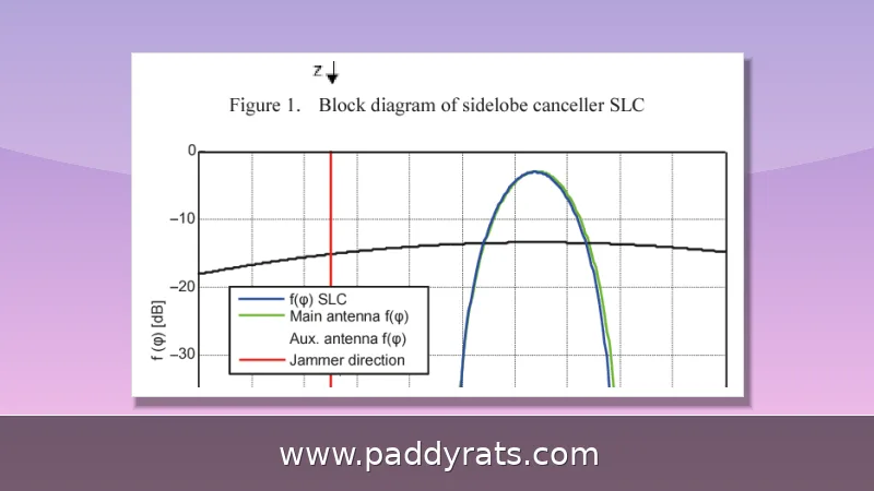
Sidelobe cancellation, or SLC, is an electronic counter-countermeasure that keeps jamming out of a radar by suppressing the interference that sneaks in through the antenna's sidelobes. Military radars have relied on it since the 1960s, and today it's still one of the most common anti-jam techniques out there—found on everything from old rotating dish systems to modern phased arrays. The concept itself isn't complicated: a handful of low-gain auxiliary antennas pick up samples of the interference around the radar, and a processor subtracts weighted copies of those samples from the main signal.
The cancellation ratio (CR) — basically how much you improve the signal-to-jammer ratio — typically lands somewhere between 20 and 40 dB. In the real world, though, things are messier: pattern mismatch between the main and auxiliary channels tends to cap actual cancellation at around 25 to 35 dB. That gap between what the math promises and what the hardware delivers is where engineers end up spending most of their time, and it's exactly why any SLC performance claim needs to be tied to a specific antenna configuration and bandwidth before you take it seriously.
People often lump SLC together with sidelobe blanking (SLB), but they're actually doing two different jobs. SLC goes after the jammer itself, suppressing it so the real target echo can still come through. SLB, on the other hand, is about catching pulses that sneak in through the sidelobes and blanking them out — its main purpose is defending against false-target jamming. These aren't mutually exclusive, either. A radar can run both at the same time, and plenty of them do.
How Does the Sidelobe Cancellation Technique Work?
The hardware itself is pretty minimal. You've got two to four small, low-gain auxiliary antennas sitting around the main radar antenna. Each auxiliary is set to have a gain roughly equal to—or just a bit above—the sidelobe level of the main antenna. The idea is that an auxiliary picks up about the same jammer signal that sneaks in through the sidelobes, but basically none of the target echo, since its gain is way lower than the main beam gain.
The SLC processor generates adaptive weights and then subtracts the weighted auxiliary signals from the main signal, following the relationship y_output = x_main - sum(w_k × x_aux_k). How are those weights chosen? They come from minimizing the output power, but with one key constraint attached: the main beam gain has to stay intact. Under that rule, the weights naturally settle into a solution that cancels out the correlated interference—in other words, the jammer—while the uncorrelated target signal passes through untouched. What you end up with is a steerable null aimed squarely at the jamming source. Meanwhile, the main antenna pattern stays exactly where it was, and the target beam is never shifted.
Each auxiliary antenna can take out one independent jammer source, which means a system with two or four auxiliaries can handle that many threats at the same time. The earliest design used just a single loop, but Howells and Applebaum later expanded it into a multiple-loop setup that could deal with several jammers at once — and that same architecture is still what most deployed systems are built on today.
How Does a Generalized Sidelobe Canceller Beamformer Differ?
A generalized sidelobe canceller (GSC) beamformer takes that same math and reorganizes it into a cleaner two-channel structure. The incoming signal gets split: one branch runs through a conventional beamformer, while the other feeds a sidelobe canceling path. From there, the algorithm pre-steers the array toward the beamforming direction and then adaptively picks the filter weights in the canceling branch.
What makes the GSC formulation so appealing is really the math behind it. When you're dealing with a single interferer, you can use the Woodbury identity to invert the spatial covariance matrix without much hassle, which matters a lot if you need the computation to run in real time. And the tooling has come a long way too. MathWorks now offers a phased.GSCBeamformer System object that implements a generalized sidelobe cancellation beamformer, so you can prototype and validate your design well before you commit to actual hardware.
MIT Lincoln Laboratory actually holds a patent on an auxiliary antenna array for wideband sidelobe cancellation. The design targets simultaneous transmit and receive (STAR) systems, and it works by pairing a primary aperture array with a secondary array whose elements are placed right next to the primary aperture. From there, each auxiliary element feeds into a variable attenuator, a variable phase shifter, or a variable true time-delay unit, and a controller adaptively adjusts the attenuation, phase shift, and delay values for every element. In effect, each auxiliary element functions as an adaptive tap of an adaptive finite-impulse response filter. The patent points out that static filtering methods simply don't offer enough accuracy, efficiency, or adaptability—and that's exactly the gap this adaptive tap structure is meant to fill.
What Limits Sidelobe Cancellation Performance?
Four failure modes dominate how well SLC actually performs in the field. The biggest one is auxiliary antenna pattern mismatch: the auxiliary pattern never lines up perfectly with the main antenna's sidelobe pattern, so cancellation typically gets stuck in the 25-35 dB range. Bandwidth mismatch comes next, and unlike pattern mismatch, it depends on frequency. When the jammer's bandwidth is wider than the cancellation loop's bandwidth, cancellation starts to fall off at frequencies away from the center of the loop.
There's also a hard limit set by the internal noise of the auxiliary receiver — no matter how well you tune the weights, you can't cancel below that floor. Multipath is the fourth constraint. When a jammer signal reaches the radar through several paths with different delays, a single-tap cancellation structure just can't keep up, since one weight can't simultaneously invert multiple delayed copies of the same signal.
There is also a stability concern. Unconstrained adaptation can distort the beam, shift the main lobe pointing, and ultimately hurt target detection. That is why the weight solution is constrained to preserve main beam gain rather than simply minimizing output power, and why margin is typically allocated for manufacturing tolerances and aging effects during design.
How Is SLC Different from Adaptive Beamforming?
The cleanest way to separate the two is by how much of the array they touch. SLC uses a few auxiliary antennas, typically two to four, to cancel specific jammers while the main antenna pattern stays fixed. Main beam direction and shape are unaffected, which matters when the radar has to keep a calibrated, known beam for tracking and measurement.
Adaptive beamforming uses the full array, all elements, to form nulls. That is more capable, but it can affect main beam shape and requires a phased array with element-level digital receivers. Retrofitting that onto an existing reflector or dish radar is usually impractical. The trade-offs are summarized below.
| Attribute | Sidelobe Cancellation (SLC) | Adaptive Beamforming |
|---|---|---|
| Antennas used | 2-4 auxiliary antennas | Full array, all elements |
| Main beam impact | None; pattern stays fixed | Can alter beam shape and gain |
| Hardware requirement | Low-gain auxiliaries plus processor | Element-level digital receivers |
| Retrofit to legacy radar | Yes, common on rotating dish radars | Generally not practical |
| Typical null depth | 20-40 dB (25-35 dB with mismatch) | Deeper nulls, higher complexity |
That table explains why SLC is the most common ECCM technique on legacy rotating dish radars. It is simpler, cheaper, and can be added to hardware that was never designed for digital beamforming. Adaptive beamforming wins when the platform is a wideband phased array from the start and the mission justifies the cost.
Can SLC Protect Against Main Beam Jamming?
No, and this is the single most important limitation to understand. SLC only cancels sidelobe jamming. If the jammer sits in the main beam, its signal is far stronger in the main channel than in the auxiliary channels, so subtracting it would also cancel the target echo. The constraint that preserves main beam gain is exactly what prevents SLC from nulling a main beam interferer.
Main beam jamming requires a different toolkit. Adaptive beamforming can place a null at the jammer direction within the main beam, at the cost of reduced gain elsewhere in the pattern. Sidelobe blanking detects and blanks main beam jammer pulses, which protects against false targets rather than recovering the real one. Burn-through, simply increasing transmit power until the target return exceeds the jammer, remains the blunt but reliable fallback.
In practice, layered defense is the norm. A radar might run SLC against sidelobe jammers, blanking against pulse jammers, and rely on waveform agility or power management when a jammer moves into the main beam.
Where Is Sidelobe Cancellation Used?
Military radar systems remain the primary application, particularly for target acquisition and tracking where sidelobe jamming is a persistent threat. The technique also shows up in telecommunications, space-based observation systems, and radio astronomy, where suppressing unwanted off-axis signals improves measurement quality. In wireless communication systems, SLC-style spatial filtering contributes to bandwidth efficiency by rejecting co-channel interference.
Weather radar is a less obvious but well-documented case. The National Weather Radar Testbed studied SLC for mitigating ground clutter, which is functionally the same problem as jamming: a strong, correlated, off-axis signal contaminating the main channel. Wideband phased array radar and reflector antennas both use variants of the approach, and mutual radar interference mitigation is an emerging application as spectrum congestion grows.
Researchers have continued to refine the technique, with contributions spanning T Hong (2021), KK Bhat (2019), CD Curtis, S Wahlgren, JE Summers (1983), KM Peterson (1984), H Krichene (2015), TL Rorabaugh (1992), T Yang (2021), and Y Huang (2023). The persistence of the topic across four decades tells you the problem has not been solved so much as steadily improved.
What Should You Check When Specifying or Verifying an SLC System?
Performance verification starts with the application requirements, not the datasheet headline. A 40 dB cancellation ratio measured in a controlled anechoic chamber may collapse to 25 dB in the field once pattern mismatch, multipath, and temperature drift are included. Ask for cancellation ratio versus frequency offset, not just a single peak number.
Environmental factors matter more than most buyers expect. Temperature range, humidity, and vibration affect long-term reliability and cause parameter drift in attenuators and phase shifters, which slowly erodes null depth. Cost versus performance trade-offs between premium and standard commercial grades are real, but so is interface compatibility: impedance, connector type, and mechanical form factor often decide whether a retrofit is feasible at all.
Finally, allocate margin for manufacturing tolerances and aging. A design that just meets the cancellation requirement on day one will not meet it in year five. Build the margin in during specification, and validate it with the same environmental profile the radar will actually see.
Frequently Asked Questions
How does sidelobe cancellation work?
Small low-gain auxiliary antennas placed around the main radar antenna pick up roughly the same jammer signal entering through the sidelobes. A processor computes adaptive weights, subtracts the weighted auxiliary signals from the main signal, and drives a steerable null toward the jammer while preserving main beam gain.
What limits sidelobe cancellation performance?
Cancellation ratio typically reaches 20-40 dB, but auxiliary antenna pattern mismatch usually holds it to 25-35 dB. Bandwidth mismatch degrades cancellation at frequency offsets, auxiliary receiver internal noise sets a floor, and multipath with different delays defeats single-tap cancellation.
Can sidelobe cancellation protect against main beam jamming?
No. SLC only cancels sidelobe jamming. If the jammer sits in the main beam, its signal is far stronger in the main channel than in the auxiliary channels, so subtracting it would also cancel the target. Main beam jamming needs adaptive beamforming, sidelobe blanking, or burn-through.
How is SLC different from adaptive beamforming?
SLC uses a few auxiliary antennas, typically two to four, to cancel specific jammers while the main antenna pattern stays fixed, so the main beam direction and shape are unaffected. Adaptive beamforming uses the full array to form nulls, which can affect the main beam shape and requires element-level digital receivers.