A practical look at how jammers work, the subcircuits inside a DIY RF jammer, and why the FCC says building or selling one is illegal in the US.
What Is a Signal Jammer and How Does It Work?
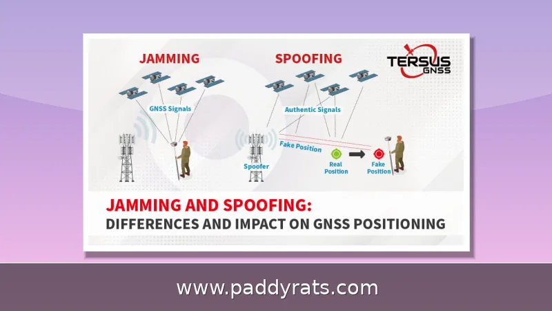
A signal jammer is really just a transmitter that intentionally drowns out other radio traffic. Instead of eavesdropping on a cell tower, it blasts noise on the same frequency a phone or Wi-Fi device is already using, so the receiver can't separate the real signal from all that interference. Take a basic cell phone jammer: it cuts the link between a handset and a base station by transmitting on the handset's own frequency band, and that same trick works against UMTS, 3G, CDMA, GSM, and PHS networks. Here's the thing, though—the jamming signal doesn't have to be louder than the tower in any absolute sense. It just needs to push the noise floor high enough that the receiver's error rate completely falls apart.
That's the thing — jamming is really a denial-of-service attack at the physical layer, not some clever hack of the phone itself. Nobody's decrypting anything, nobody's stealing data; the connection just falls apart. This same weakness is why LoRaWAN networks, which tons of IoT sensors rely on, can get knocked out by jamming attacks that sever communication between end nodes. A 2025 university paper on reactive jamming against LoRaWAN actually pushes for more research so future devices can be built to hold up better against it. And on the flip side, there's a jammer detector guide that walks you through what a world without dependable wireless comms would really look like — think hospitals, dispatch systems, and navigation all struggling at once.
Core Subcircuits: RF Amplifier, VCO, and Tuning Circuit
Every jammer circuit really comes down to three subcircuits that have to work together: an RF amplifier, a voltage controlled oscillator, and a tuning circuit. Picture a short chain, where each stage leans on the one before it. The oscillator generates the carrier at whatever frequency you're targeting, the tuned circuit locks onto that frequency and keeps it steady, and then the amplifier boosts it up to a level strong enough to actually drive an antenna. In the classic textbook version of this setup, the RF amplifier stage uses transistor Q1 along with capacitors C4 and C5 and resistor R1 to amplify the signal coming out of the tuned circuit. From there, the amplified output heads to the antenna through capacitor C6, which pulls double duty—it blocks DC and lets only the AC signal through. That coupling capacitor does more than it looks like: take it out, and DC from the amplifier would ride along to the antenna and mess up the radiation pattern.
The tuned circuit is basically just a capacitor (C1) and an inductor (L1) paired together. When they work in tandem, they act like an oscillator with next to no resistance, so as soon as you feed them energy, they ring at a high frequency and barely lose any of it to damping. What's actually happening is a continuous exchange: the voltage held in the capacitor pushes current into the inductor, the inductor stores that energy as a magnetic field, and then it hands it right back to the capacitor. That back-and-forth resonance is really the whole trick behind the design—it's what lets a handful of cheap parts generate a usable carrier signal instead of just sitting there dead. The tricky part is getting the LC ratio right. Choose the wrong capacitor or inductor value and you'll either get a circuit that won't oscillate at all or one that drifts off frequency as the components heat up. That's precisely why most builders adjust a 22pF trimmer and verify peak resonance with a voltmeter instead of just trusting their calculations.
DIY Build Options: Arduino 433 MHz, NE555, and RF Jammer Circuits
If you're looking for the easiest way into jamming hardware, the Arduino 433 MHz build is probably the one you've seen in most hobbyist write-ups. The parts list is tiny: an Arduino board, a 433 RF module, and a 12-volt supply. The Arduino itself isn't doing much—it just outputs a single square wave that feeds the RF module, which then radiates a carrier on the 433 MHz band. That simplicity is a double-edged sword. On one hand, both parts are dirt cheap and carried by basically every electronics retailer, so a beginner can throw the whole thing together on a breadboard in an afternoon. On the other hand, the waveform is pretty crude and the output power is low, so you're realistically looking at a few meters of range, not the hundreds of meters people sometimes picture. A second common route ditches the microcontroller for a transistor-based RF jammer built around a flyback driver, which swaps easy assembly for more output and a little more tuning work. Then there's the NE555 timer approach, the one that shows up in low-cost cell phone jammer projects—it's about as bare-bones as an oscillator gets, and people usually pick it when they want the cheapest possible proof of concept rather than something they'd actually rely on.
One cell phone jammer project in the source material tuned to 450 MHz, while a mobile jammer circuit is said to block signals out to 100 meters under favorable conditions. That gap is worth sitting with for a second, because it tells you published range claims swing wildly depending on antenna gain, the power supply, and whatever the surrounding environment happens to be. Realistically, a simple jammer circuit will jam a wide range of RF signals somewhere between 5 and 10 meters, and that's about the scale a hobbyist should expect from a breadboard build.
Components, Coil Specs, and Antenna Tuning
If you've ever wound a flyback transformer before, these RF jammer build notes will probably feel like familiar territory. First, wind the primary and secondary coils the same way, then drop in a fast diode to keep voltage surges from frying the transistor. And don't cut corners on the heatsink—go too small and that transistor will start heating up almost immediately. When you get to the flyback primary and secondary coils, use screws instead of solder. You'll also want to build a rigid paper cylinder and glue the coils onto it, making sure the ferrite cores are positioned correctly with plastic plates separating them.
Coil specs are where a lot of first-time builders get tripped up, and honestly, it's easy to see why. Most people start with 1 mm thickness paired with 0.1 mm magnetic wire, presoaked in paraffin wax — the wax bath helps hold the windings steady so they don't shift once things heat up. If you want a coil that can survive higher temperatures without turning into a puddle, epoxy is the more melt-resistant option, though it's messier to work with. Add a secondary coil and you can pull 8–9 mm sparks, but that doesn't come free: it needs a 20W power supply to actually deliver. Then there's peak resonance, which is really just a tuning ritual. Hook up a 0–10V DC voltmeter across the circuit, turn the 22p trimmer until the needle peaks at a maximum reading of 3V, then carefully fine-tune it back down to land on the proper frequency. An ideal RF jamming device uses 22pF trimmers and covers 50 MHz to 1 GHz, but try to jam around 500 MHz and stability issues tend to creep in — a good reminder that covering a wide band and holding steady at one frequency are two very different goals.
Range, Power, and Frequency Coverage
Range is the first thing every builder wants to know, and honestly, it's the hardest thing to answer without hedging. A DIY RF jammer with a 2-meter antenna will usually get you somewhere in the 10–15 meter ballpark, and in one build that was actually documented, the spark length went from 2–3 mm up to about 8 mm once the antenna was attached — a handy visual proxy for the extra output you're actually getting. Sure, a longer antenna stretches your range, but medium-wave noise has a habit of creeping in at longer distances, while VHF noise tends to show up most around 8–10 meters. Secondary coils help extend range too, and if you beef up the performance drivers, the whole system benefits.
Once you look at actual builds side by side, those spec numbers stop feeling abstract and start looking like a series of trade-offs. A basic circuit might only get you 5 to 10 meters, while a carefully tuned mobile jammer can hit 100 meters—but that kind of jump usually means bigger coils, more power, and a lot more heat to deal with. Throw in a longer antenna and the range climbs again, though MW noise tends to show up at distance and VHF noise gets worst around 8 to 10 meters. Power is just as critical: a heatsink that's too small will have a transistor overheating within minutes, and a secondary coil putting out 8 to 9 mm sparks typically needs a 20W supply behind it. Frequency coverage is its own balancing act. An ideal RF jammer with 22pF trimmers covers 50 MHz to 1 GHz, but trying to force one to jam around 500 MHz usually creates stability issues, which is why a lot of cell phone jammer projects just settle on 450 MHz as the tuning frequency. The table below brings these practical trade-offs together.
Frequency Bands and Typical Coverage of DIY Jammers
| Build type | Typical frequency | Reported range | Main limitation |
|---|---|---|---|
| Arduino + 433 RF module | 433 MHz | Short, room scale | Crude square-wave output |
| NE555 timer jammer | Varies with RC network | Several meters | Drift and low power |
| Transistor RF jammer | 450 MHz tuning example | 5-10 meters | Heat and tuning stability |
| Mobile jammer circuit | Multi-band | Up to 100 meters claimed | Power supply and antenna size |
| Ideal RF jamming setup | 50 MHz to 1 GHz | Depends on antenna | Instability near 500 MHz |
Treat that table as a set of claims, not promises. The 100-meter figure doesn't come from thin air—it traces back to one specific circuit description, and it quietly assumes a clean power supply and a properly matched antenna. On a first build, you rarely get either. The 5–10 meter figure is the more honest expectation for a breadboard circuit, where stray capacitance, wobbly solder joints, and a noisy bench supply all eat into performance. The 50 MHz to 1 GHz coverage is just as conditional. It only holds if the 22pF trimmers are actually tuned at peak resonance—verified with a voltmeter reading around 3V before fine-tuning back to the target frequency—rather than twisted into place by eye and hope. Skip that step, and the claimed range collapses fast.
SDR and HackRF Approaches to Signal Generation
Software-defined radio has completely changed the game for anyone who wants to experiment with signal generation without ever picking up a soldering iron. Instead of winding coils and tuning trimmers by hand, you let software define the waveform. The HackRF is one of the most accessible tools for this, capable of generating signals from 10 megahertz all the way up to 6 gigahertz — a span that covers everything from FM broadcast and GSM up through Wi-Fi, Bluetooth, and beyond. Pair it with the PortaPack add-on, and you get a handheld setup with a screen, buttons, and battery power. Loading HAVOC custom firmware onto that combination unlocks FSK tone sweep modes and a set of presets, so you can jump between signal types without rebuilding a circuit. Jerry Olla's HackRF and PortaPack demo is a good look at how far a handheld SDR setup has come, and Keith Parsons has covered related wireless testing topics at WLPC for anyone who wants more context on the testing side.
A practical SDR build starts by loading custom firmware such as HAVOC onto a HackRF paired with a PortaPack, then adding a screen, physical buttons, a touchscreen, and a battery so the whole unit can run untethered in the field. From there, you configure the signal generation modes and presets directly in the firmware, which means the hardware itself barely changes from one experiment to the next — only the software settings do. Contrast that with winding a flyback transformer, presoaking coils in paraffin wax, and hunting for peak resonance with a voltmeter and a 22p trimmer, and you can see why SDR has become the default for modern RF testing and research. The HackRF alone tunes from 10 MHz to 6 GHz, and HAVOC's FSK tone sweep modes and presets let you jump between targets in seconds. That flexibility is exactly the problem: a general-purpose SDR can transmit on bands a hobbyist has no authorization to touch, so the same tool that makes legitimate research easier also makes the legal line easiest to cross.
Is It Legal to Build or Use a Signal Jammer?
In many countries signal jamming is illegal, and the United States is unambiguous about it. The FCC warns that it is a violation of federal law to use, market, or sell jammers that block authorized radio communications such as cell phones, police radar, GPS, and Wi-Fi. Consumers cannot legally use jammers in the United States, and retailers cannot lawfully sell them. The agency has kept up enforcement alerts on this topic, and the legal exposure applies to the seller as much as the operator.
There are narrow exceptions for federal government use, but they do not extend to hobbyists, landlords, or businesses that want quiet phones in a conference room. If the goal is to stop distracting notifications, the lawful tools are policy and software: airplane mode requirements, MDM profiles, and network-level controls. If the goal is RF research, the lawful path is a shielded enclosure or a licensed test range. For anyone weighing a build, the compliance question comes before the parts list, not after.
What Should a Beginner Expect From a First Jammer Build?
Expect a short-range, unstable result. Forum users regularly ask for a tutorial to create their own cell phone signal jammer, and a YouTube comment asks about building a circuit for 4G and 5G bands with about 5 meters of range. That 5-meter target is realistic for a first attempt; the multi-band coverage is not. Higher bands need better components, tighter tuning, and more careful shielding than a hobby build typically provides.
The bigger lesson from the source material is that jamming is a well-understood engineering problem with well-understood limits. The hard part is not making interference; it is making interference that stays on frequency, does not overheat, and does not spill into bands you never intended to touch. That is why serious work in this area happens in shielded rooms and licensed test setups rather than on a kitchen table.
Frequently Asked Questions
<h3>How does a signal jammer work?</h3><p>A jammer transmits on the same frequency as the target device, creating strong interference between the transmitter and receiver. A basic cell phone jammer combines an RF amplifier, a voltage controlled oscillator, and a tuning circuit to block networks such as UMTS, 3G, CDMA, GSM, and PHS.</p><h3>What components are needed to build a simple jammer?</h3><p>Common DIY builds use an Arduino with a 433 MHz RF module, or a transistor-based circuit with resistors, capacitors, an inductor, and an antenna. An RF jammer guide lists a heatsink, flyback driver, hard paper, glue, and paraffin wax as key materials.</p><h3>Is building or using a signal jammer legal?</h3><p>In many countries signal jamming is illegal. The FCC states it is a violation of federal law to operate, market, or sell jamming equipment that blocks authorized radio communications such as cell phones, police radar, GPS, and Wi-Fi, and retailers cannot lawfully sell them in the United States.</p><h3>What frequency range can a DIY RF jammer cover?</h3><p>A simple jammer circuit can block radio frequency signals over 5 to 10 meters. An ideal RF jamming setup uses 22pF trimmers and covers 50 MHz to 1 GHz, though forcing it to jam around 500 MHz may cause stability issues.</p>
Frequently Asked Questions
How does a signal jammer work?
A jammer transmits on the same frequency as the target device, creating strong interference between the transmitter and receiver. A basic cell phone jammer combines an RF amplifier, a voltage controlled oscillator, and a tuning circuit to block networks such as UMTS, 3G, CDMA, GSM, and PHS.
What components are needed to build a simple jammer?
Common DIY builds use an Arduino with a 433 MHz RF module, or a transistor-based circuit with resistors, capacitors, an inductor, and an antenna. An RF jammer guide lists a heatsink, flyback driver, hard paper, glue, and paraffin wax as key materials.
Is building or using a signal jammer legal?
In many countries signal jamming is illegal. The FCC states it is a violation of federal law to operate, market, or sell jamming equipment that blocks authorized radio communications such as cell phones, police radar, GPS, and Wi-Fi, and retailers cannot lawfully sell them in the United States.
What frequency range can a DIY RF jammer cover?
A simple jammer circuit can block radio frequency signals over 5 to 10 meters. An ideal RF jamming setup uses 22pF trimmers and covers 50 MHz to 1 GHz, though forcing it to jam around 500 MHz may cause stability issues.