Multi-band signal jammer design combines a voltage-controlled oscillator, RF amplifier, and tuning circuit to deny several cellular bands at once. Here is how the circuits work, what real hardware specs look like, and why US law treats consumer jammers as off-limits.
What Is a Multi-Band Signal Jammer and How Does It Work?
A multi-band signal jammer is basically a transmitter that blasts strong interference onto the same frequencies a target network is using, so nearby phones can't reliably send or receive data. Rather than covering just one channel, these designs hit several cellular bands at the same time — which is why you'll also see them called multiband mobile phone jammers, RF jammers, or signal blockers. The key point is that a single-band blocker falls apart the moment an operator moves traffic to another frequency, whereas a multi-band unit keeps the pressure on across the whole set of bands that operator depends on.
At its core, a jammer works through deliberate interference. It radiates energy on the same frequency the mobile handset is using, which raises the noise floor high enough to break the link between caller and receiver. A 2025 IEEE paper by S Nakul walks through a controlled multi-band jammer built for cellular networks, covering 2G, 3G, and 4G FDD-LTE, and it relies on a voltage-controlled oscillator, an RF amplifier, and a tuning circuit. Earlier academic work points in much the same direction. A 2015 Auburn thesis by G Hughes describes a short-range multi-band frequency jammer designed to take on CDMA850 (851–894 MHz) and GSM900 (925–960 MHz).
Coverage is never universal, and that's really the core engineering constraint you have to design around. Take the Yasar University project — it used a 900–1900 MHz span to cover GSM900, GPS, and GSM1800 for wide-band or multi-band jamming. That single choice shows how much band selection drives the entire bill of materials. And since mobile networks run on so many different frequencies — 850, 900, 1800, 2100, and 2300 MHz in India alone — designers have to pick which bands actually matter for their deployment and just accept the gaps everywhere else. Meanwhile, operators keep adapting to dodge noisy bands, so a jammer that can't handle frequency agility tends to age out fast.
Core Building Blocks: VCO, RF Amplifier, and Tuning Circuit
Every practical design comes down to three subcircuits: an RF amplifier, a voltage-controlled oscillator, and a tuning circuit. The VCO generates the carrier, the tuning circuit sets and stabilizes the operating frequency, and the RF amplifier boosts the signal to a usable output level before it ever reaches the antenna. In a simple teaching circuit, transistor Q1 turns on a tuned circuit made up of capacitor C1 and inductor L1. That tuned circuit acts as an oscillator, producing a high frequency with minimal damping while energy swings back and forth between the capacitor and the inductor.
The oscillator is really the heart of the whole thing—if it isn't stable, the jammer won't stay locked on the frequency you're targeting. When a VCO drifts, it spills energy outside the band you meant to hit, which wastes power and creates out-of-band emissions that regulators come down on hard. For tuning, people usually go with variable capacitors or varactor diodes, and DIY RF jammer builders often rely on 22pF trimmers to cover a range from 50 MHz up to 1 GHz. To find peak resonance, you hook a 0–10 V DC voltmeter between the test point and ground, then adjust the 22p trimmer until you get a maximum reading of around 3 V—after that, you fine-tune it back to the correct frequency.
Passive components deserve just as much attention as the active devices here. Inductors are usually made by winding enameled copper wire around a bolt of the needed diameter, then sliding the coil off the form—one example in the literature calls for a 2.2 nH inductor and a 1 nH inductor. On the low-power side, a DIY module built around the CC1101 chip gives you a sense of how small this can get: 3.3V input, a max operating speed of 500 kbps, support for 2-FSK, GFSK, and MSK modulation, and ISM/SRD coverage at 315, 433, and 868 MHz. None of these parts jam anything on their own, obviously, but they demonstrate just how compact an RF front end can be.
Jamming Techniques: Spot, Sweep, Barrage, and DRFM
Jamming techniques fall into two main categories: noise techniques and repeater techniques. Under the noise umbrella, you get spot, sweep, and barrage jamming. Spot jamming puts all your power on a single frequency—great if you're targeting something known and fixed, but pretty much useless against frequency-agile radar. Sweep jamming, on the other hand, moves that full power across a range of frequencies in rapid succession, so each individual channel only gets hit for a moment. Barrage jamming goes after multiple frequencies simultaneously, but since the power gets divided among them, the strength at any one frequency drops. That trade-off is exactly why you can't have both wide coverage and high per-channel power at the same time.
Repeater techniques work differently. DRFM, which stands for digital radio frequency memory, captures incoming radar energy, modifies it, and sends it back out to create false targets — it's the go-to repeater method in modern electronic attack. Which approach you pick comes down to the threat model: noise denial is simpler and cheaper to build, whereas DRFM requires fast sampling, plenty of memory, and very precise timing. When it comes to cellular denial, noise techniques tend to win out, since the whole point is to raise the noise floor rather than trick a receiver.
Defenses have evolved right alongside the jammers themselves. Multi-band resilient radios can switch frequencies in real time whenever they detect interference, congestion, or jamming, relying on automatic band switching and spectrum scanning to stay connected. Frequency hopping does help against narrowband jamming, but it's not a cure-all — wideband and adaptive jamming can target the entire band at once, and simply cranking up transmit power won't get you out of a contested band. Systems like Doodle Labs Mesh Rider radios, Red Cat Teal systems, and JEM Engineering products are all built around this idea of resilience, which is exactly why relying on single-band denial is a losing strategy.
Typical Frequency Bands and Output Power Specifications
When you look at published hardware specs, you start to see what multi-band coverage actually looks like in a real commercial product. Take the Action ATJ8-78-28: it's a pretty typical eight-channel unit, and its numbers are worth paying attention to because each band is tied to a specific measured output level rather than just a vague frequency range. The table below pulls together the headline parameters from the manufacturer's spec sheet.
| Parameter | Specification |
|---|---|
| Total RF output power | Max 65 W across 8 channels |
| Bands and output | 2500-2570 MHz (38.5 dBm), 1805-1920 MHz (39 dBm), 925-960 MHz (42.3 dBm), 2400-2500 MHz (38.4 dBm), 2110-2170 MHz (38.5 dBm), 790-826 MHz (39.2 dBm), 2620-2690 MHz (39.2 dBm), 851-894 MHz (40.8 dBm) |
| Per-channel output | 7-10 dBm/30KHz |
| Power and consumption | AC220V input, 200 W power consumption |
| Physical and environment | 10 kg, 300x200x150 mm, 30%-95% humidity, -20 to +55 Celsius |
| Jamming area | Up to 150 m |
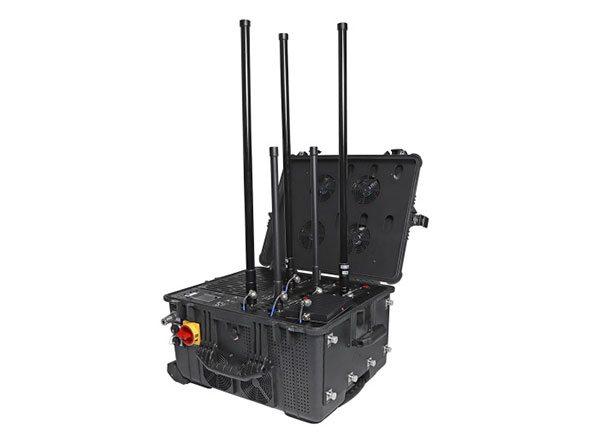
Other hardware fills different niches. A high-power multi-band jammer listed by Intercept.ws runs on roughly 230VAC or 110VAC, uses an external high-gain omnidirectional antenna, reaches an active range of 500 m, and covers 6 bands. The JM33-F988 manual describes a unit with 12 independent channels, which shows how channel count scales separately from band count. A US patent, US7697885B2, filed by Aeroflex on 2006-09-15 and granted on 2010-04-13, describes a multi-band jammer with a tone comb generator, a dwell time shorter than a GSM burst period, concurrent transmit and receive band jamming, and about 20 mW of jamming signal power.
Real-world performance rarely matches the marketing sheet. A discussion on Reddit's r/sdr community suggests expecting a 20-30 dB loss with a poorly designed jammer, which is a useful reality check on range claims. DIY builds sit at the opposite extreme: a typical guide targets 5-10 m of jamming, and with a 2 m antenna the sparks reach about 8 mm with a range of 10-15 m. VHF noise is most prevalent at 8-10 m. Those figures describe bench experiments, not fielded systems, and they underline how much antenna design and impedance matching affect the outcome.
Design Trade-Offs: Power, Range, Cooling, and Antenna Layout
Power, range, cooling, and antenna layout form a tightly coupled system, and improving one usually degrades another. Barrage jamming covers multiple frequencies at once but is less powerful at any single frequency, so a designer chasing wide coverage pays in effective range. Spot jamming is ineffective against frequency-agile radar, and frequency hopping works against narrowband jamming, which means the target's agility sets the minimum bandwidth the jammer must cover. Multi-band systems provide fallback, redundancy, and global deployment readiness that single-band radios lack, and that flexibility is the main reason the architecture persists.
Thermal design is where ambitious specs meet physics. A 200 W power draw in a 10 kg, 300x200x150 mm enclosure leaves little margin for continuous duty, and DIY guides recommend a large heatsink for exactly this reason. Builders are also warned to install a fast diode to shield the transistor, avoid solder on flyback connections, build a rigid paper cylinder, place ferrite cores with plastic plates between them, and presoak the coil in paraffin wax before final assembly. Those steps reduce arcing and insulation breakdown at high voltage.
Antenna layout deserves the same discipline as the RF chain. A high-gain omnidirectional antenna can extend range, but poor impedance matching wastes power and can reflect energy back into the amplifier. Switching on a jammer before all antennas are connected can damage the equipment, and VSWR circuit protection guards against antenna short circuiting or disconnection. In short-range DIY designs, the secondary coil runs about 1 mm thick with 0.1 mm magnetic wire, produces 8-9 mm sparks, and requires a 20 W supply, all of which illustrates how quickly small geometry changes alter the electrical stress on the circuit.
Regulatory and Safety Considerations for Jammer Design
In the United States, the FCC states that RF jammers are prohibited for consumer use and cause an inability to use multiple wireless systems on various bands. Enforcement actions target both the sale and the operation of these devices, and the prohibition is not limited to cellular frequencies. Because jammers can interfere with emergency communications, the JM33-F988 manual itself emphasizes legal usage, which is a notable admission from a product documentation set. Legal deployment is generally limited to authorized government or military contexts.
The technical risks compound the legal ones. Jamming a band does not discriminate between a phone call and a 911 call, and it can disrupt Wi-Fi, GPS, and public safety radios sharing nearby spectrum. For engineers, the practical takeaway is that design knowledge and deployment authority are separate questions. Studying VCO behavior, amplifier linearity, and antenna matching is legitimate RF engineering; building and operating a transmitter that denies licensed spectrum is not, unless you hold explicit authorization.
Market forecasts show why enforcement matters. Technavio forecasts growth of USD 1.08 billion at a CAGR of 5.66% between 2023 and 2028, while Fortune Business Insights projects the market growing from $4.98 billion in 2026 to $9.27 billion by 2034 at a CAGR of 8.1%. Those figures cover the broader signal jammer market, including authorized government and defense demand, and they should not be read as a green light for consumer devices. Terminology in this space, including multiband jammer, RF jammer, signal blocker, jamming antenna, barrage jamming, spot jamming, sweep jamming, DRFM, and spectrum denial, describes capabilities that remain tightly controlled.
How Do You Approach a Multi-Band Jammer Circuit Design in Practice?
A disciplined design process starts with the target band list, not the circuit. Once the bands are fixed, the VCO range, tuning network, and amplifier bandwidth follow from that decision. The next step is the driver circuit, followed by winding the primary and secondary coils the same way, installing a fast diode to shield the transistor, and mounting a large heatsink. A rigid paper cylinder and ferrite cores separated by plastic plates keep the high-voltage section stable, and presoaking the coil in paraffin wax improves insulation before the antenna is connected.
Testing should be incremental and instrumented. Peak resonance is confirmed with a 0-10 V DC voltmeter between the test point and ground, adjusting the 22p trimmer for a maximum reading of about 3 V before fine-tuning back to the target frequency. Inductors are made by winding enameled copper wire over a bolt of the required diameter and then removing the winding, with values such as 2.2 nH and 1 nH appearing in one example. Each stage should be verified before the next is powered, because a single miswired connection can destroy the RF amplifier.
One simple circuit is never enough for a real deployment. Mobile networks use many frequencies, and operators adapt to avoid noisy bands, so coverage has to be planned against a moving target. Portable jammers work by overpowering the targeted signal frequency and preventing nearby users from sending or receiving data, which is precisely why they are regulated so heavily. Treat every design exercise as a study in RF engineering and interference physics, and treat deployment as a licensing question that only authorized operators can answer.
Frequently Asked Questions
How does a multi-band signal jammer work?
It generates strong interference on the same frequencies used by target networks, overpowering the signal so nearby devices cannot send or receive data. Typical designs combine a voltage-controlled oscillator, an RF amplifier, and a tuning circuit, then transmit through antennas covering several bands. Because the noise floor rises across the whole set of bands, frequency-agile radios lose their fallback options.
What are the main jamming techniques?
The two main techniques are noise jamming and repeater jamming. Noise jamming includes spot, sweep, and barrage jamming. DRFM is the most common repeater technique, altering and re-transmitting received radar energy to create false targets. Spot jamming concentrates power on one frequency, sweep jamming moves full power across frequencies quickly, and barrage jamming covers multiple frequencies at once at lower per-frequency strength.
Are signal jammers legal to build or use?
In the United States, RF jammers are prohibited for consumer use under FCC rules, and enforcement actions target their sale and operation. Jammers can also interfere with emergency communications, so legal deployment is generally limited to authorized government or military contexts. Studying jammer circuit principles is legitimate RF engineering, but building and operating a transmitter that denies licensed spectrum without authorization is not.
What frequency bands can a multi-band jammer cover?
Coverage varies by design. Examples include 851-894 MHz, 925-960 MHz, 1805-1920 MHz, 2110-2170 MHz, 2400-2500 MHz, 2500-2570 MHz, 2620-2690 MHz, and 790-826 MHz, plus optional bands such as GPS, Wi-Fi, and 433 MHz. Real hardware ties each band to a measured output level, so the band list and the amplifier budget have to be planned together.