Digital RF Memory (DRFM) captures an incoming radar signal, digitizes it, and replays a coherent copy to fool an enemy radar. It is the core of modern electronic attack, and the market behind it is growing fast.
What Is a Digital RF Memory (DRFM)?
A Digital RF Memory, often abbreviated to DRFM is a capture and playback electronic technique for digitising an incoming RF signal and replaying it later on demand [6]. It samples this signal at the frequency and bandwidth or resolution sufficient to represent it digitally, stores those digits in memory, and reconstructs the waveform when requested later. The reason being that it flows naturally into the radar's own processing chain, since the copy is made from what looks like a real threat signal rather than this synthesized guess. DRFM hardware, in practice, is installed within radar and electronic warfare (EW) systems where it enables jamming deception and false target generation. The term is also written out as Digital Radio Frequency Memory, with both forms meaning the same thing.
How Does a DRFM Work?
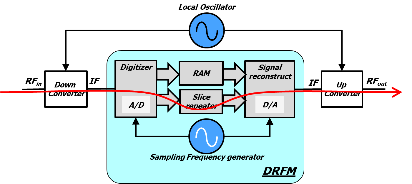
The mechanism that works is a repeatable chain, Receive → Translate → Digitize -> Store —> Rebuild. The most common form of DRFM operates by translating RF down to baseband, passing the signal through a high-speed ADC which samples and writes the digitised values in memory followed by reconstructing this downstream via DAC. DRFM distinguishes itself from older analog approaches in that delay, phase, and frequency are all digitally controlled. The delay can be short enough to make a target look like it is moving, or long enough that an false echo appears miles from the real one. The U.S. Navy's SBIR FY2013. 1 topic N131-006 examined direct digital RF conversion DRFM with input frequencies in the 2 GHz to 18 GHz range — dispensing altogether with some of those earlier analog translation steps.
DRFM System Components and Architecture
DRFM is not one Chip, but a small system. It typically consists of a receiver with varying features, transmitter signal processing digital memory information acquisition and part component electronic countermeasures (ECM). The foundation of the hardware is a combination of broadband RF front-end components, high-speed digitization modules and low-latency FPGA processing boards; while at its core, the DRFM kernel built around FPGAs, ADCs and DACs. Such an architecture makes the DRFM a central part of a super-heterodyne selective receiver, which is actually the fundamental response channel design for jammer systems. Memory depth matters because larger storage is needed for longer delays, whereas short delays can be managed via the use of FIFOs. A design project sponsored by Blackwire Signals and run at Utah State University incorporated longer delays coupled with DDR memory (a case where a bypass mode was needed to accept only FIFOs), gain before transmission, and switching from various multiple data streams.
DRFM Techniques: Deception, Spoofing and Jamming
Once a signal is captured and stored, the DRFM can bend it in ways that throw off an adversary's tracking loop. Coherent replicas are built from the same signal the threat radar sent out—that received pulse becomes the seed for the jamming signal. Because of this, the jamming signal looks just like the real echo and gets processed with the same processing gain, which pushes the jamming-to-signal (J/S) ratio higher. These replicas are what make deception techniques work: shifting range through Range Gate Pull Off (RGPO) and Pull In, or shifting speed through Velocity Gate Pull Off and Pull In. The stored signal can also seed noise modulation, generating spot noise that's tailored to the radar's instantaneous frequency bandwidth or Doppler bandwidth—what's known as coherent spot noise. And when you use the received, stored signal as the RF carrier instead of a locally synthesized one, the jamming noise performs better and lines up more closely with the radar's bandwidth.
Coherent vs Non-Coherent DRFM Replicas
The majority of the engineering value resides in differentiating between coherent and non-coherent operation. The noise from a non-coherent repeater or even adapted simple false realities are still generated but its character fails to preserve the phase coherence so modern radars can often filter this out. A coherent DRFM holds phase and frequency constant, enabling the jammer to steer a radar's range gate or velocity gate in a controlled manner. Digital methods enhance spectral purity and decrease the DRFM signature, making it less detectable by removing spurious spectral components. Since the replica has an identical processing gain to that of a realistic echo, it appears legitimate and is treated as such by the radar. This is why DRFM has been slowly phasing out the older style recirculating Frequency Memory Loop (FML) in next-generation jammer designs.
DRFM Specifications and Comparable Parameters
Platform specifications differ widely, but numbers published provide a good;general( indication of the range. The AN/ULQ-21(V) jammer generates noise and deception techniques from 850 MHz to 18 GHz, while the Navy SBIR direct-digitization effort focused on input between 2GHz and frequencies up to at least 18 GHz[3]. For test-equipment, take a look at the Rohde & Schwarz FSWX analyzer with analysis bandwidth of 8 GHz (single-channel mode) and for two channels up to 4 GHz per channel, plus supported by KM700 pulse-analysis software together with VSE-K6 pulse-analysis option. The table below gives an overview of the most important numbers.
| Parameter | Specification | Source / Platform |
|---|---|---|
| Frequency range | 850 MHz to 18 GHz | AN/ULQ-21(V) jammer |
| Direct digitization input | 2 GHz to 18 GHz | Navy SBIR FY2013.1, topic N131-006 |
| Analysis bandwidth | Up to 8 GHz single-channel; 4 GHz per channel dual-channel | Rohde & Schwarz FSWX analyzer |
| RF converter modules | One to six | MoDREx |
| Micro-DRFM modules | One to 12 | MoDREx |
| Simultaneous emitters tracked | As many as 12 time-coincident emitters | MoDREx |
| DRFM kernel building blocks | FPGA, ADC, DAC | General DRFM architecture |
Those numbers explain why DRFM modules are often characterized in terms of channels and simultaneous emitters rather than just raw bandwidth. If a platform can track 12 time-coincident emitters then it is able to do much more than simply replay one pulse, but actually control an antenna in real-time within a dense electromagnetic environment. Built on that modular philosophy, they're products like the MoDREx (modular digital receiver exciter) and DCM6222 (/digital transceiver/reader)/ from Mercury Systems--which gives designers design flexibility to scale converter [and][1]/ /designs of their photonic backbone system 9.driving electronics.
Testing and Validating DRFM Jammers
Testing is where DRFM programs live or die, because a deception technique that looks correct on paper can fail against a real radar. Key parameters include amplitude fidelity, phase-coherence, time delay, spectral integrity, group delay, modulation quality measured through error vector magnitude (EVM) and I/Q imbalance, and spur and intermodulation characterization. Together these assess deception effectiveness from signal reception all the way through retransmission. Statistical pulse analysis over time captures and analyzes pulses so engineers can see whether the replica drifts. Range testing remains expensive, often costing tens of thousands of dollars per hour, which is why lab-based validation with instruments like the FSWX has become so important. A 2025 Microwave Journal article on advanced testing of next-generation DRFM jammers reflects how much attention this step now receives.
Market Growth, Contracts and Industry Players
The commercial picture is expanding alongside the technology. The DRFM market was valued at $1.6 billion in 2025 and is projected to reach $3.13 billion by 2034, a 7.8% compound annual growth rate, according to Dataintelo. Government spending backs that trend: the U.S. Navy announced a $243.8 million contract to Mercury Systems for DRFM units plus incidental teardown, repair, and upgrades to the AN/ULQ-21(V), with work in Cypress, California, scheduled to finish by February 2029. Mercury Systems (Andover, Massachusetts), including Mercury Defense Systems, formerly KOR Electronics, is a major supplier. Other names in the field include Systems & Technology Research (STR) of Woburn, Massachusetts; the Georgia Tech Research Institute, whose Angry Kitten system is associated with DRFM design expertise; Rohde & Schwarz of Munich, Germany; and the Naval Air Warfare Center Weapons Division at China Lake.
Training, Security Clearance and Program History
Access to the deepest DRFM knowledge is deliberately restricted. The Georgia Tech DRFM course is classified, and attendance is limited to U.S. citizens with the appropriate security clearance and a need-to-know; contractors also need a U.S. Government sponsor's or contracting officer's signature. That gatekeeping reflects how sensitive coherent jamming techniques are. The public record stretches back decades: a 1986 paper on Digital Radio Frequency Memories by Hey-Shipton, a 1990 paper by Roome, the 2013 Navy SBIR topic, a 2016 design and implementation paper by Yin, and a 2020 paper by Davidson. More recent milestones include the March 2024 Mercury contract and a December 2025 Microwave Journal piece on advanced testing of next-generation DRFM jammers. Anyone entering the field should expect both a steep technical curve and a compliance one.
Frequently Asked Questions
What is a Digital RF Memory (DRFM)?
A DRFM is an electronic method for digitally capturing and retransmitting RF signals. It digitizes an incoming RF input at the frequency and bandwidth needed to represent the signal, then reconstructs it when required. DRFM systems are typically used in radar and electronic warfare jamming.
How does a DRFM jammer work?
DRFMs digitize incoming RF signals, store them, and retransmit them with precise control over delay, phase, and frequency. This enables techniques such as false target generation, range gate pull-off, velocity deception, and coherent spoofing to manipulate an adversary's radar.
What are the main components of a DRFM system?
DRFM systems generally consist of a receiver, transmitter, signal processing, digital memory, and an ECM control system. Hardware typically includes broadband RF hardware, high-speed digitization modules, and low-latency FPGA processing boards, with ADCs and DACs in the DRFM kernel.
What parameters are tested in a DRFM?
Key DRFM testing parameters include amplitude fidelity, phase-coherence, time delay, spectral integrity, group delay, modulation quality (EVM and I/Q imbalance), and spur and intermodulation characterization. These assess deception effectiveness from signal reception through retransmission.