5G NR interference splits into internal and external sources, and the uplink is where it hurts most. Here is how RF engineers measure, hunt, and mitigate it in TDD networks.
What Is 5G NR Interference and Why Does It Matter?
In 5G New Radio, interference is any unwanted energy that shows up in the same time and frequency resources the network is trying to use. You won't see it flagged by some obvious alarm — instead it quietly drags down throughput, drops connections, and causes access failures. From the gNB's point of view, the uplink signal is extremely weak, so even a small amount of interference can cut off communication between the UE and the network. That imbalance explains why operators end up spending far more time in the field chasing uplink problems than downlink ones.
The magnitude of the challenge is not academic. In a measurement-study published via arxiv in August 2025 (2508.20060), they found out that each cell has at the very least one interfering bumch neighbor and virtually all UEs are affected as properly Approximately [30,60] of 4G BSs and [40−70%](≤[20U)[200and inline mobiles/>times/1000× can experience intra-BS inter-cell interference, leading to a large number UEs experiencing such kind (or lower) of Interference levels. The deployment of over five million 5G base stations across the world has transformed interference work into an operational discipline — not a just-a-thing-we-do-from-time-to-time edge case.
Internal vs External Interference: What Is the Difference?
Interference falls into two main categories: internal and external. Internal interference comes from within the network itself — think overlapping cells, pilot pollution, or TDD sites that aren't properly time-synchronized. External interference, on the other hand, originates from sources outside the network, such as faulty satellite LNBs for TV reception, rooftop solar panels, engines, power supplies, transformer stations, and power inverters. These two types call for entirely different approaches: internal issues are typically resolved through parameter adjustments and antenna changes, while external ones require tracking down the physical source.
The importance of the distinction lies in the commonality of symptoms. One faulty satellite LNB or one failing power inverter cranking up the noise floor of an entire sector might look just like a capacity and/or coverage issue. Field teams that decide to tune the radio parameters avoid an external emitter often spend multiple days trying to fix something which was never a problem in the configuration of their radio. I call the internal-versus-external question — my first branch in every troubleshooting tree.
Why Is the 5G NR Uplink So Sensitive to Interference?
For the uplink, we have a much weaker signal than in your downlink. The fact that a handset transmits at only 1/100th of the power (than what is radiated from a gNB), and this signal reaches the base station after being attenuated by propagation loss distance, building loss and body-loss. Since the received uplink signal is down at, or near, the thermal noise floor very few dB of additional interference will lower our desired response to below that which an error free decoding can be achieved in the receiver. That noise translates, practically/in practice, to a few dB of spare power = no cell-edge uplink throughput at all.
This is how unsynchronized NR TDD sites have the potential to cause DL-to-UL interference, in which one base station's downlink transmission falls within a neighbor&aposs uplink receive window. This characteristic that antennas are physically close to one another and hence coupling is high due to co-location, makes the effect stronger. That is the essence of how 3GPP created remote interference management (RIM) — when a base station recognizes increasingly distant depravity, it sends out an uncommon RIM reference signal and standardized method rapidly counteracts far-off uplink weakening.
How Do You Measure Interference in 5G NR TDD Networks?
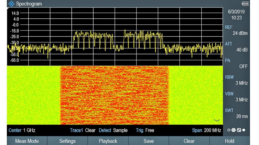
TDD Uplink Interference Hunting Start with Reading p system information ( Get the Tdd Periodicity, Slot Configuration and Symbol allocation ) You synchronize the scanner to that TDD pattern, and put a time gate so the instrument only samples energy during uplink slots. For instance, the R&S Spectrum Rider FPH handheld analyzer supports a gated trigger - in zero span mode you'll see uplink and downlink slots at once so you set up your gate to land within an uplink slot for clean uplink spectrum measurement.
Rohdeースchwarz provides specifications that can act as a reference for this type of workflow. The R&S TSMx network scanner family provides a panoramic view of up to +/-100 MHz from the 5G SSB center frequency and hunting view bandwidths (up to 9.6 MHz). As a real-world example, 3.5 GHz center frequency with N78 measurement of 100 MHz bandwidth and subcarrier spacing equal to kHz can run for up to hours (999 h)! And this is what determines that intermittent interferers are catchable in waterfall mode!
| Tool | Key specification | Field use |
|---|---|---|
| R&S TSMx scanner | Panoramic view up to +/-100 MHz from SSB center; hunting view up to 9.6 MHz | Wideband survey and targeted uplink hunting |
| R&S Spectrum Rider FPH | N78, 3.5 GHz center, 100 MHz bandwidth, 30 kHz SCS; waterfall recording up to 999 h | Gated-trigger uplink isolation and long captures |
| R&S FSH / ZPH / ZVH | Handheld analyzer family | General field interference monitoring |
| Keysight RTSA-capable analyzer | Real-time spectrum analysis | Transient and short-duration emitter detection |
First load the gate, and then in practice you walk sector with a directional antenna while tone is on: more interferer power = higher pitch in phone. Audio feedback means you can triangulate a source without staring into the screen. Because swept analyzers can miss these short bursts all together, a real-time spectrum analyzer is the better tool for transient electromagnetic interference.
What Is Inter-Cell Interference and How Common Is It?
Inter-cell interference is unwanted signal from neighboring cells landing in the resources your serving cell is using. It becomes severe in dense deployments, where 5G densification increases throughput but also exacerbates inter-cell interference, especially in dense urban areas. The August 2025 arXiv measurement study quantified this: every cell had at least one interfering neighbor, about 60% of 5G base stations suffered intra-BS inter-cell interference, and around 70% of UEs were affected. Those numbers explain why SINR, not RSRP, is the metric that predicts real user experience.
RSRP measures coverage strength, RSRQ is a proxy for interference, and SINR is the link-adaptation input. RSRP and SINR vary independently, and high RSRP does not prove high SINR. A UE can sit at -80 dBm RSRP and still deliver poor throughput because three strong neighbors are competing for the same resources. This is why I always pull SINR per receive antenna before touching any transmit power setting.
What Is Passive Intermodulation (PIM) in 5G Networks?
PIM occurs when multiple signal frequencies interfere in non-linear passive components like antennas and cables, generating spurious signals that prevent the receiver from decoding wanted signals. It can cause increased call drops, reduced data throughput, and diminished network capacity. Because 5G NR uses wider bandwidths, up to 400 MHz for a single carrier, more transmit frequencies mix inside the same passive hardware, which raises both the odds and the severity of PIM products.
PIM is usually a hardware problem, not a parameter problem. Loose connectors, corroded joints, metal-to-metal contacts, and damaged feeders are common culprits. MCV Microwave, based in Laurel, Delaware, publishes a PIM white paper and offers a PIM test tool covering 700 MHz to 7500 MHz with 30 dB gain. When a site shows a raised noise floor that tracks with its own transmit power, PIM is the first hypothesis I test, because the interference scales with the site's own downlink rather than with an external emitter.
How Do You Optimize SINR and Diagnose Hardware Faults?
SINR optimization starts with diagnosing pilot pollution, which I define as three or more cells with RSRP above -95 dBm and no dominant server. The fixes are mechanical and parameter-based: reduce transmit power on secondary cells, increase electrical down-tilt by +1 to +3 degrees, adjust azimuth to reshape the coverage footprint, review frequency allocation, and consider ICIC or eICIC with Almost Blank Subframes where the architecture supports it. Each change should be followed by a fresh SINR measurement rather than assumed to work.
Hardware fault detection is simpler than most teams make it. Compare SINR per receive antenna across Rx0, Rx1, Rx2, and Rx3. A single degraded Rx path points to an antenna connector or cable issue, not to a radio parameter problem. For deeper measurement, the Qualcomm DIAG interface exposes packet 0xB193 for LTE LL1 serving cell measurement with SINR per Rx antenna, 0xB97F for 5G NR L1 serving cell measurement, and 0xB17F for LTE ML1 connected mode neighbor measurement. Those three packet types cover most day-to-day uplink and neighbor analysis.
How Do You Choose Between Band Strategies and Duplex Modes?
Band choice is a trade-off between coverage, capacity, and interference risk. Low-band below 1 GHz, including 600, 700, and 850 MHz, gives coverage and indoor penetration but lower speeds. Mid-band from 1 to 6 GHz, including AWS, PCS, WCS, 2.3 GHz, 2.5 GHz, CBRS at 3.5 GHz, and C-band at 3.7 to 4.2 GHz, balances coverage and capacity. High-band and mmWave at 24 GHz and above, including 28, 37, and 39 GHz, delivers extreme speeds but short range and obstruction sensitivity, which requires dense small cells.
| Band tier | Typical bandwidth per channel | Typical output power | Interference profile |
|---|---|---|---|
| Low-band (<1 GHz) | ~10-20 MHz | ~40-60 W | Wide coverage, fewer cells, lower inter-cell risk |
| Mid-band (1-6 GHz) | 50-100 MHz | ~20-30 W | Balance point, moderate inter-cell interference |
| High-band / mmWave (24 GHz+) | 400 MHz up to 800 MHz or more | ~1-3 W per channel | Dense small cells, high inter-cell and blockage risk |
Duplex mode changes the hunting workflow more than any other single factor. FDD uses different frequencies for uplink and downlink, so interference hunting is straightforward. TDD uses the same frequency for both directions, so downlink masks uplink and a gated trigger becomes mandatory. 5G NR itself uses OFDM with scalable numerology at 15, 30, 60, and 120 kHz subcarrier spacing, and wider spacing reduces interference sensitivity because symbols are shorter and more robust to delay spread. Peak rates reach up to 20 Gbps downlink and 10 Gbps uplink, with higher frequency ranges cited up to 100 Gbps.
What Do Transient EMI Studies Tell Us About Real Deployments?
Not all interference is continuous. A January 2025 arXiv study (2501.11389) examined transient electromagnetic interference and found that LTE-A and 5G-NR links degrade under transient EMI from catenary-pantograph contact in railway environments, with degradation proportional to interference gain. The researchers scanned between 2.194 and 2.2045 GHz and identified the most EMI-sensitive center frequencies, with interference gains set at 12 dB and 15 dB. The takeaway for operators near rail corridors is that a clean average noise floor can still hide damaging bursts.
This is where long-duration waterfall recording earns its keep. A capture that runs for hundreds of hours will catch events that a five-minute sweep misses entirely. Combined with a gated uplink trigger, it turns an intermittent complaint into a documented, timestamped interference signature that a mitigation team can actually act on.
Frequently Asked Questions
What are the main types of interference in 5G NR networks?
Interference is split into internal and external types. Internal interference comes from the network itself, such as overlapping cells or a lack of time synchronization. External interference originates from outside sources like faulty SAT LNBs, solar panels, engines, power supplies, transformer stations, and inverters. The two categories require different troubleshooting tools and fixes.
Why is uplink more vulnerable to interference in 5G NR TDD?
From a gNB perspective the uplink is an extremely weak signal, so even low interference levels can completely interrupt communication between user equipment and the network. In TDD, downlink and uplink share the same frequency, and downlink signals mask the uplink. Unsynchronized TDD sites can therefore create DL-to-UL interference that remote interference management is designed to address.
How do you separate uplink and downlink when hunting interference in TDD networks?
Handheld analyzers such as the R&S Spectrum Rider FPH support a gated trigger. In zero span mode uplink and downlink slots become visible, and users configure a gate that falls into an uplink slot, producing a clean uplink spectrum measurement. You first read the TDD periodicity and slot allocation from system information, then synchronize the instrument to that pattern.
What is passive intermodulation (PIM) and why does it matter in 5G?
PIM occurs when multiple signal frequencies interfere in non-linear passive components like antennas and cables, generating spurious signals that prevent the receiver from decoding wanted signals. It can cause increased call drops, reduced data throughput, and diminished network capacity. Because 5G NR supports up to 400 MHz per carrier, more frequencies mix inside the same passive hardware, making PIM both more likely and more damaging.